PhobGCC 1.2 Build Guide
This is an illustrated guide to making a PhobGCC 1.2, using photos taken of a PhobGCC board version 1.2.2.
If you want to see it in motion, watch the PhobGCC 1.2 Assembly Video.
If you are very skilled with your hands, it is certainly possible to build a PhobGCC as your very first soldering project.
But if you are new to soldering, it’s highly recommended to get a soldering practice kit to build your physical understanding of the soldering process with before you start and potentially ruin a PhobGCC board, Teensy, and GCC components.
Tools
It’s possible to work with cheap tools and supplies if you’re very skilled.
But if you cheap out on solder or soldering iron “because you’re just a beginner” you will be in for a lot of pain and suffering.
Come to the Discord server for advice on what to get if you’re at all unsure.
Required Tools
- Temperature-controlled soldering iron with a moderate size chisel tip. DO NOT USE AN UNCONTROLLED TEMPERATURE IRON!
- Flux-core solder, ideally no-clean flux (SAC305 ideally)
- No-clean rosin flux paste (not to be confused with solder paste)
- Tri-Wing screwdriver and small Phillips or ideally JIS driver set
- Sharp tweezers
- Flush cutter (the closer to flush they cut, the better)
- Pliers
- Solder sucker (or more sophisticated desoldering tool)
- Vise or PCB support (the alligator clip kind is not very useful)
- Multimeter for debugging
- 90%+ rubbing alcohol and cotton swabs
Suggested Tools
- Non-magnetic tweezers, if you’re not using printed magnet holders
- Anti-static mat/grounding strap
- Fume fan
Parts
Some of the parts are taken from a donor Gamecube controller, while others must be sourced new. Check the PhobGCC Ordering Guide for a list of what you need to purchase.
New Parts
- PhobGCC 1.2 board (includes C-stick board and may have two trigger paddles)
- Teensy 4.0 without headers
- Headers
- 4x Hall Effect sensors
- 4x magnets
- Either superglue or 3D-printed magnet holders
- Optional 4x D-pad buttons
- Optional 4x mouse buttons for ABXY (assembly not depicted)
- Optional 1x or 2x mouse buttons for triggers (assembly not depicted)
Internal Parts Harvested from Donor GCC
Not counting the shell, buttons, stick caps, etc.
- 2x Stickboxes
- 2x Trigger potentiometers
- Cable (or make or buy your own)
- Rumble Motor (or use a cellphone rumble)
- Rumble Bracket (or source your own 3D-printed one)
- Z-button switch
- Optional: trigger paddles with attached wires
For the desoldering process, start at slide 5 of the PhobGCC 1.1 Build Guide or watch the first section of the PhobGCC 1.2 Assembly Video.
Build Process
Magnet Mounting
If you’re using superglue to mount magnets to the stickboxes, consult slide 16 of the PhobGCC 1.1 Build Guide. You want to do this before the rest of the process, preferably a few hours before.
If you’re using 3D-printed magnet holders, you can do this right before putting the stickboxes on the board. First press-fit the magnet holders over the pegs on the stickboxes, add a thin coat of superglue inside the magnet holder, then press-fit the magnets themselves into the magnet holders. Consult this section of the PhobGCC 1.2 Assembly Video.
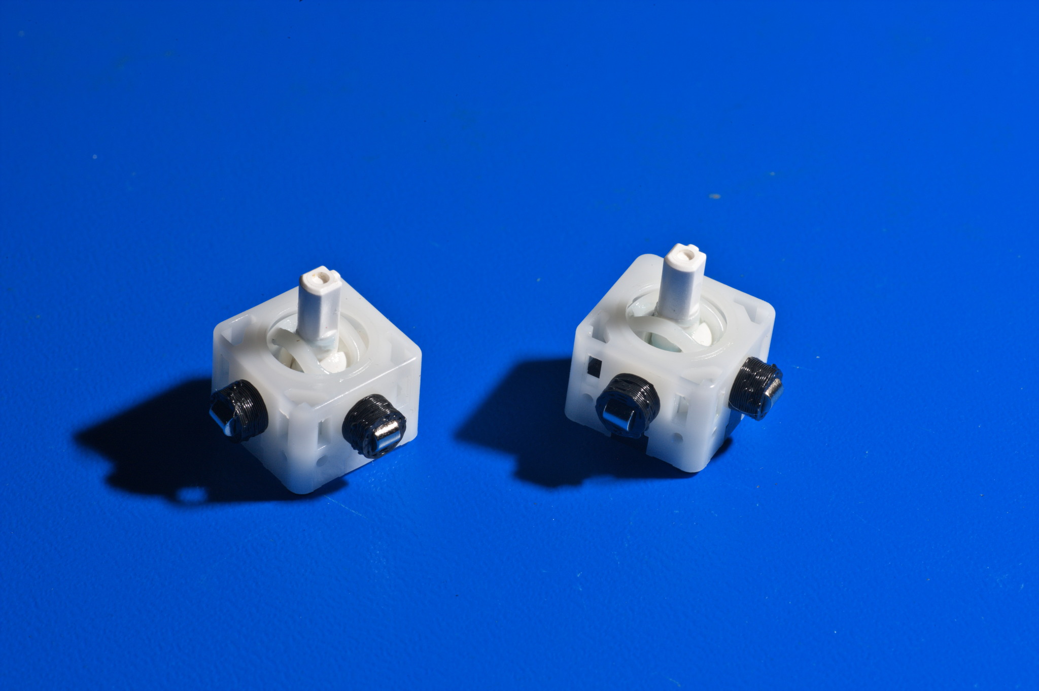
Make sure the magnets are oriented horizontally.
Soldering Interlude
Many people attempting to build PhobGCCs are new or relatively novice solderers. In this section I outline the basic processes and techniques involved in soldering in the hopes of making the process go more smoothly.
Soldering is basically applying fancy conductive hot glue to the surfaces, with some important differences. The first difference is that the parts that are getting soldered together must be very hot in order for the solder to stick. Additionally, the parts that are being soldered are usually damaged by too much heat, or heat applied for too long. Finally, the oxidation on the surface of the metal must be stripped off somehow.
These must all be considered together in order to successfully solder.
Heating
First, in order to properly heat the joint, you need to heat the joint to above the melting temperature of the solder. This involves a few considerations.
First is the melting temperature of the solder, which you use to determine the iron temperature.
- Leaded Sn63Pb37 solder melts at 183C/361F, and is usually soldered with the iron at 315-340C/600-650F.
- Lead-free SAC305 (Sn 96.5%, Ag 3%, Cu 0.5%) solder melts at a higher temperature of 217C/423F, and is usually soldered with the iron at 340-370C/650-700F.
If you set the iron too cold, it takes too long to heat the joint to a sufficient temperature, and nearby parts may be overheated and damaged. Conversely, if you set the iron too hot, the joint itself can be overheated and this can cause damage to the pads on the PCB or lift traces. I recommend you use the lower end of the temperature scales I listed as a starting point.
The second consideration is your soldering iron and its tips.
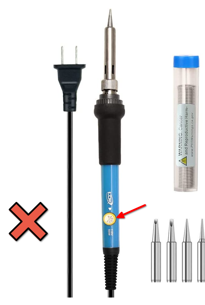
Make sure you are using a temperature-controlled soldering iron that can be set to specific temperatures, not just power levels. If it’s not temperature-controlled, just don’t use it. A non-controlled iron will heat up to hotter than you want when it’s not being actively used, and cool down to lower than you want when it’s being used. It’s not worth the suffering involved. You will hate the iron, hate yourself, and in all likelihood end up with nonfunctional PhobGCCs.
Do not use the following kind of soldering iron with the tiny dial on the handle. I call these “Phob Destroyers” because they do not have actual temperature control. They are cheap, and you get what you pay for: garbage.
Next is the tip size. In general, you want to get the most contact between the tip and the solder joint without touching adjacent joints. Ideally, you use a chisel tip that is exactly as wide as the pads. Most people don’t switch soldering iron tips frequently, so in this case you should select the widest tip usable for the smallest joints. On the PhobGCC 1.2, the smallest joints are the Hall effect sensors, which have pads 0.8mm wide. I recommend you use a chisel tip from 0.8 to 1mm wide, ideally. I actually use a 1.6mm wide tip, which works better for the larger pads but is slightly more difficult to use for the Hall effect sensors.
Additionally you have to consider tip condition when heating. When metal is left at a high temperature, the metal surface reacts with oxygen in the air to form an oxide layer that insulates the tip, preventing heat transfer, and also doesn’t let solder stick to it. It is important to keep the tip tinned with fresh solder or tip-tinner whenever it is not in use. While the solder oxidizes, it is also liquid at operating temperature so any oxidation of it can be easily wiped off with a wet sponge before beginning to solder. If the tip has oxidized significantly, you can scrub off the oxide coating using a brass wool sponge, followed immediately by dipping the tip in tip tinner or alternatively coating the tip with normal solder. If you aren’t using your iron for a while, make sure to turn it off to stop it from oxidizing.
Finally, it comes down to technique. In order to transfer the heat as effectively as possible, apply a lot of pressure using the soldering iron to both parts that you want to join together. The board is robust, so you can press down on it very hard, and press across onto pins as hard as you can without bending them, which may vary based on the pin thickness.
Removing Oxidation from Surfaces
While oxidation quickly grows thick on very hot metal like the soldering iron tip, a thin layer exists on almost every metal. To remove this, a material called flux is applied. When flux is heated, it becomes reactive and strips the oxygen out of the metal oxides. This lets the solder bond properly to the surface.
Most solder has a flux-core, where flux is actually inside the solder wire so that it is automatically applied when you melt the solder. Do not get solder that is “solid wire”. There are various kinds of flux as well. You should get no-clean rosin flux. More active flux types are useful when soldering to different materials, but you don’t need any more than no-clean rosin flux for the gold-plated board of the PhobGCC. If you do use more active types of flux, then you need to clean the board off after soldering in order to prevent corrosion.
In addition to flux core, if you are having trouble, you can add additional flux, which can come as a gel, a liquid in a syringe or bottle, or in a pen. I personally find that I have no need for these, but some find it very helpful.
To effectively use flux-core solder, you must apply solder to the joint, not to the iron. If you apply solder to the iron, all the flux gets used up on the surface of the iron and there’s no effect on the joint surfaces that you want to bond to. Additionally, if you apply solder to the joint and not to the iron, you can be sure the joint is hot enough before the solder is applied. Another benefit is that this lets you better control the amount of solder. If you touch the solder onto the iron tip, you might end up with a big blob of solder on the iron tip and none on the board.
General description of technique
First, turn on the iron and wait for it to heat up.
Then, for each joint:
- Scrub off oxidation on soldering iron tip with brass wool.
- Tin the tip with solder or tip tinner.
- Clean most of the tinning off the tip with brass wool or wet sponge.
- Strongly press the tip against both parts that are being soldered together.
- Apply flux-core solder wire to the joint between the two parts without touching it to the soldering iron tip.
- Wait for the solder to melt, then feed the wire in until it forms a concave cone. Do not apply too much.
- Continue heating a second or two more to let the flux in the joint stop bubbling.
- Remove the soldering iron and let the joint cool without blowing on it.
- Continue with other adjacent joints.
- When you’re done soldering for now, clean the tip with brass wool or sponge.
- Apply fresh solder or tip tinner.
Cleaning Flux
If you leave flux behind from soldering, it can cause problems. One thing is that the flux residue itself can be conductive, which can cause the Hall sensors to not work properly. This is especially problematic with flux that isn’t labeled as No-Clean. Additionally, the flux residue is corrosive and can cause the components to corrode long-term.
To remedy this, use rubbing alcohol (as high concentration as you can get) with a cotton swab to clean the flux residue from the PCB when you’re done soldering.
Teensy Programming
Begin by programming the Teensy 4.0 according to this guide.
Teensy Soldering
See this section of the PhobGCC 1.2 Assembly Video.
Insert two 14-pin strips and one 2-pin strip of low-profile header pins into the top of the board, long ends down.
Place the already-programmed Teensy 4.0 atop the header pins, then solder the Teensy to the pins.
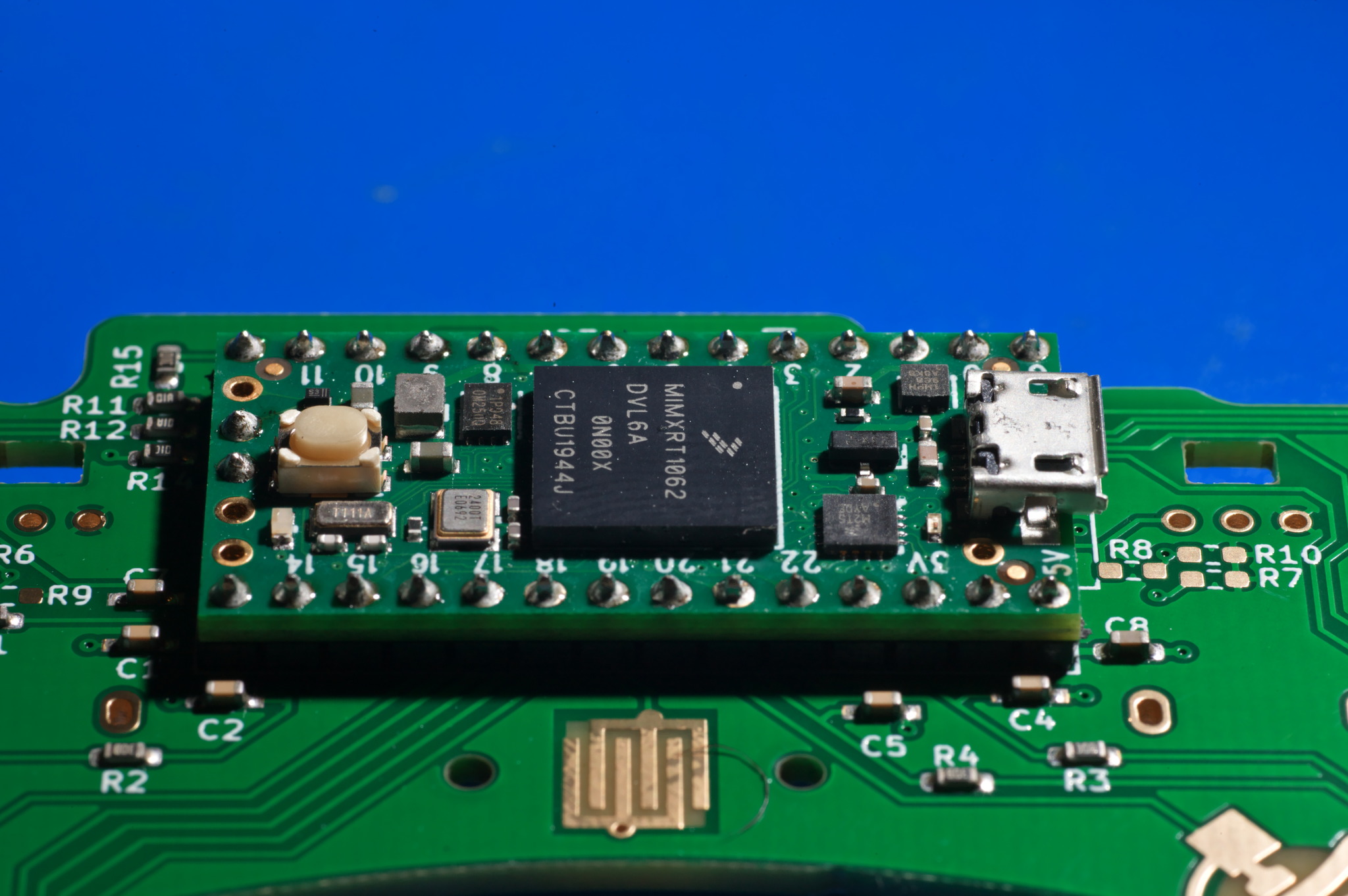
Next, flip the board over and either support the board by the Teensy or securely tape the Teensy to the board so that the pins stick up.
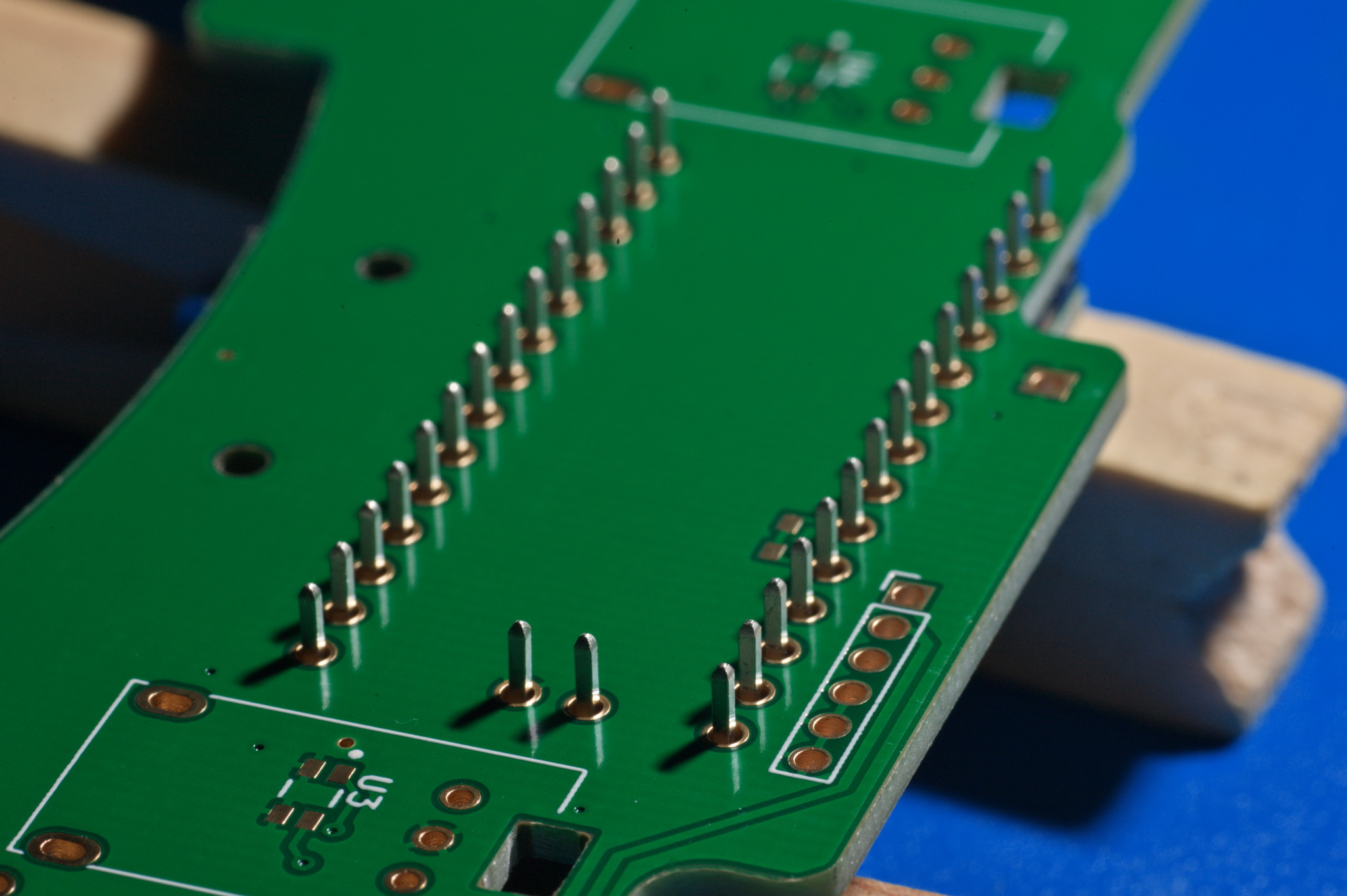
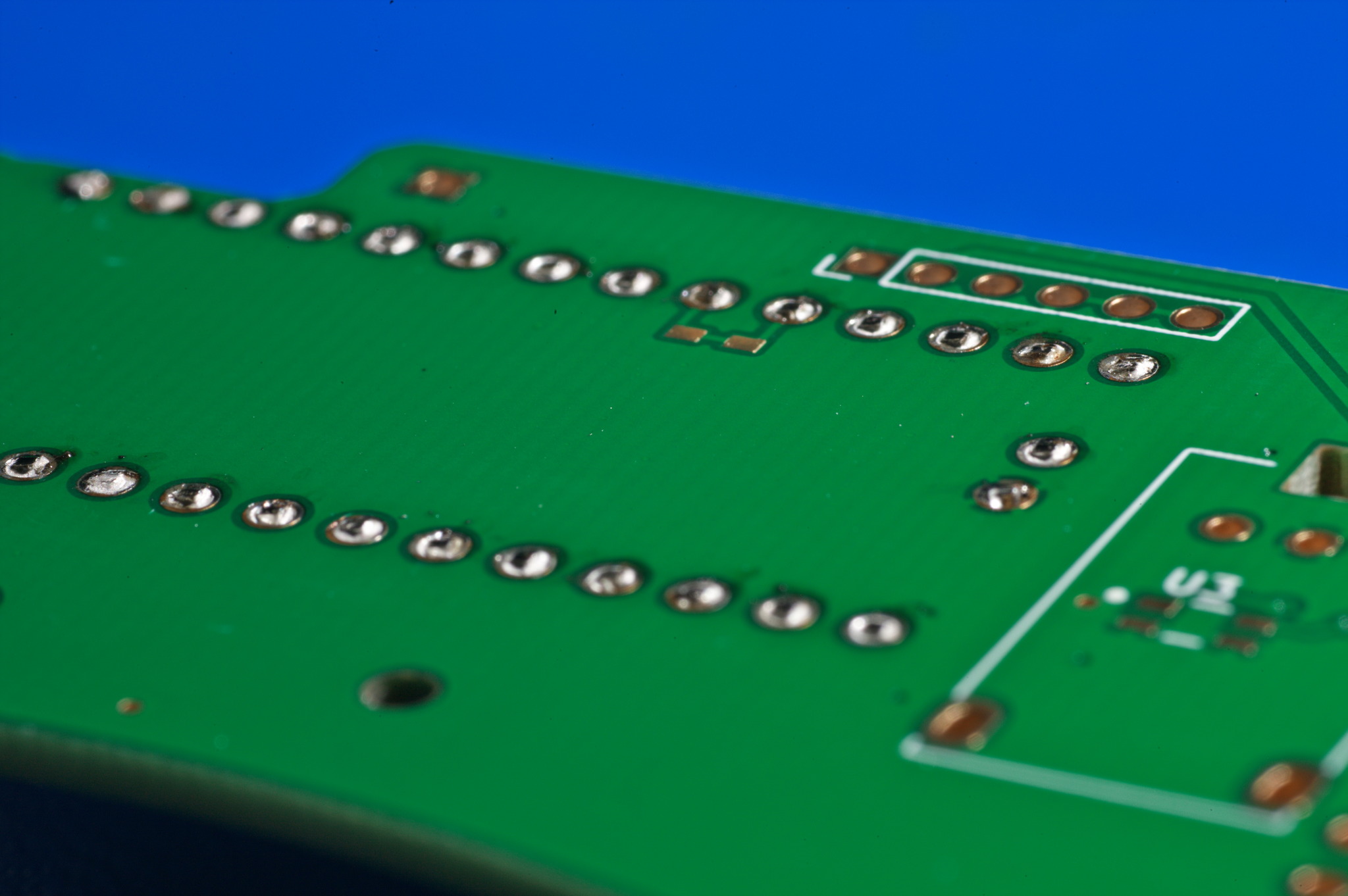
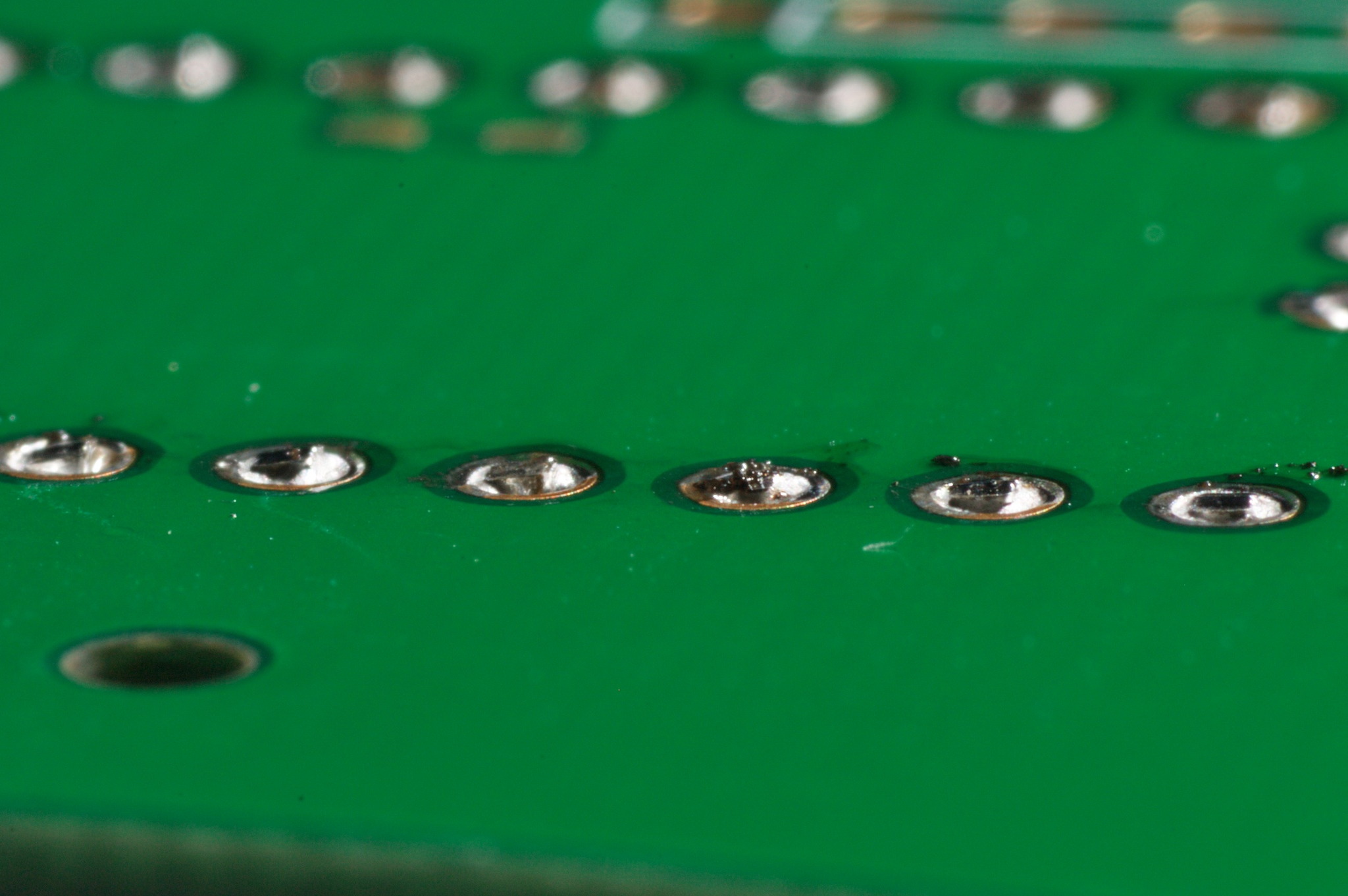
Cut the pins as flush as possible to the back of the board. If you don’t cut these flush, the rumble bracket may not fit well and the shell won’t close easily.
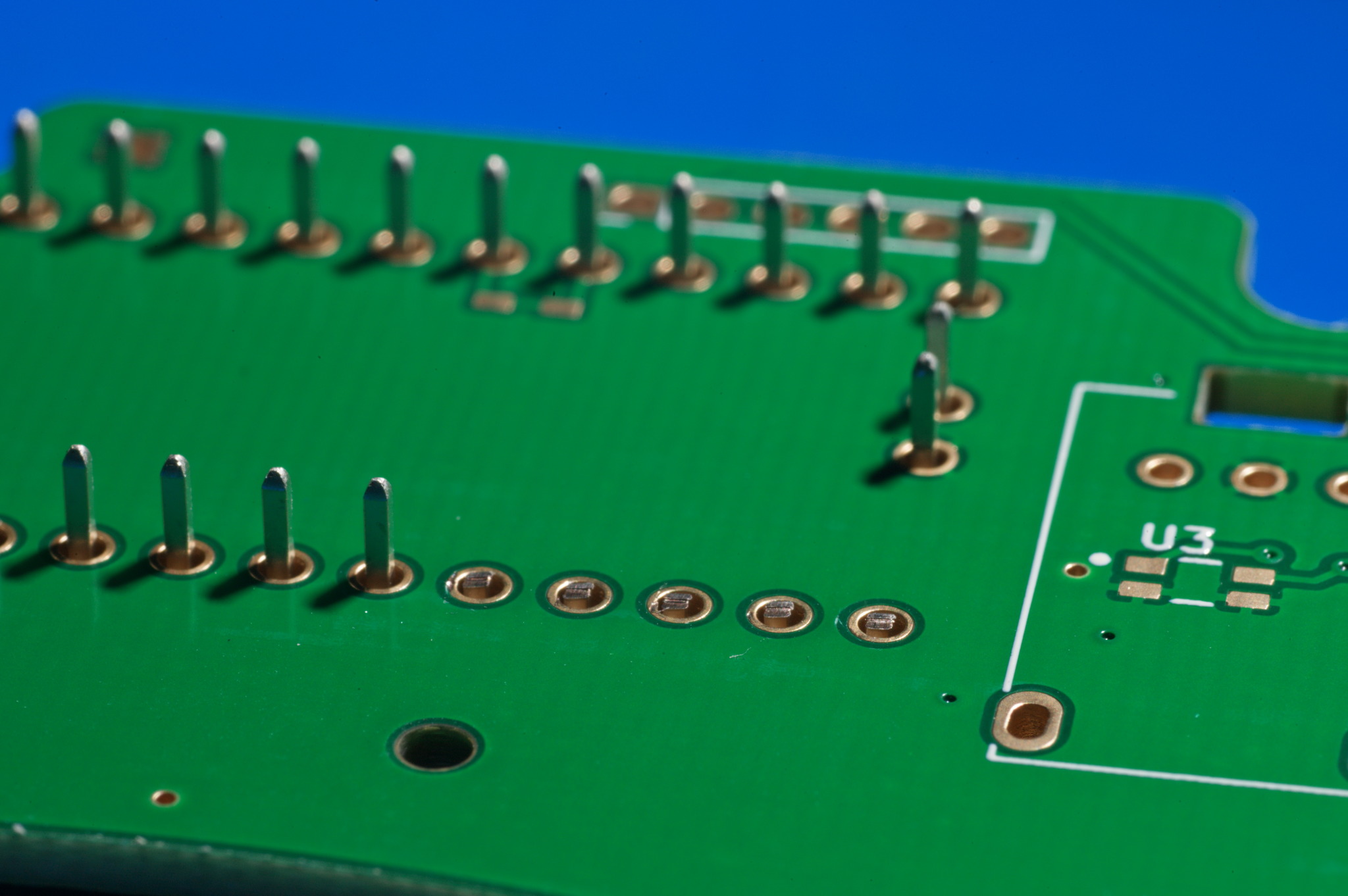
Solder the pins to the board, making sure the Teensy remains flush to the board and the vias that the pins reside in are not overfilled with solder.
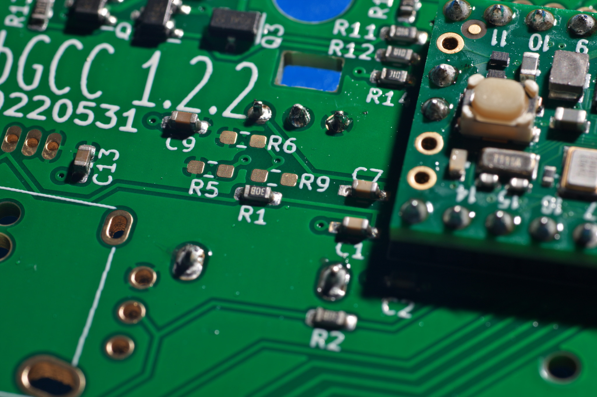
Trigger Potentiometer Soldering
See this section of the PhobGCC 1.2 Assembly Video.
Mount the trigger potentiometers to the back of the board. Do not mount them to the same side as the Teensy.
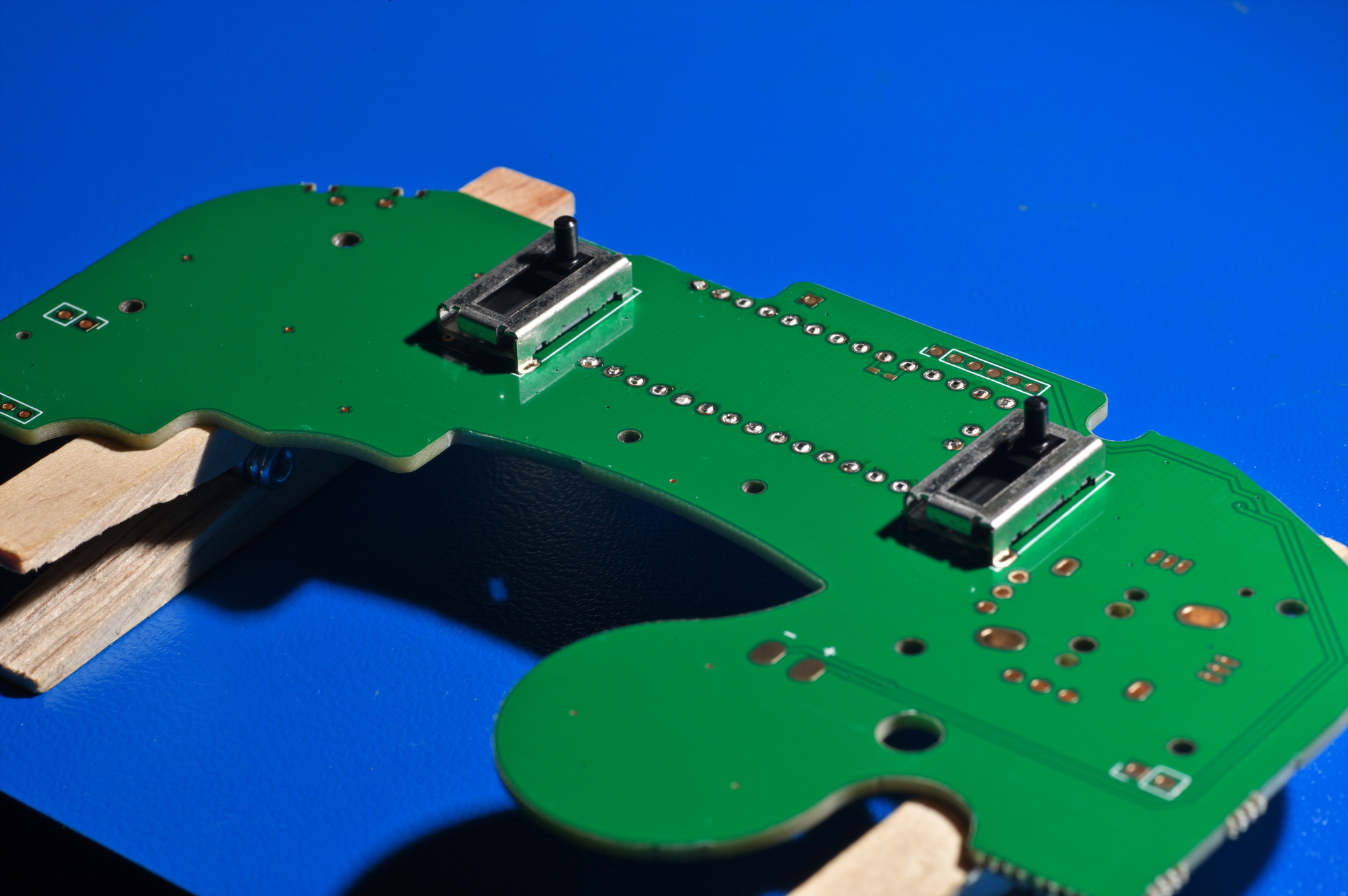
You can tape them to the board with masking tape to keep them in place, or just rest the board on top of the potentiometers to secure then in place while you solder them.
Z-button Switch Soldering
See this section of the PhobGCC 1.2 Assembly Video.
Mount the Z-button switch to the top of the board, the same side as the Teensy. Do not mount it to the back of the board.
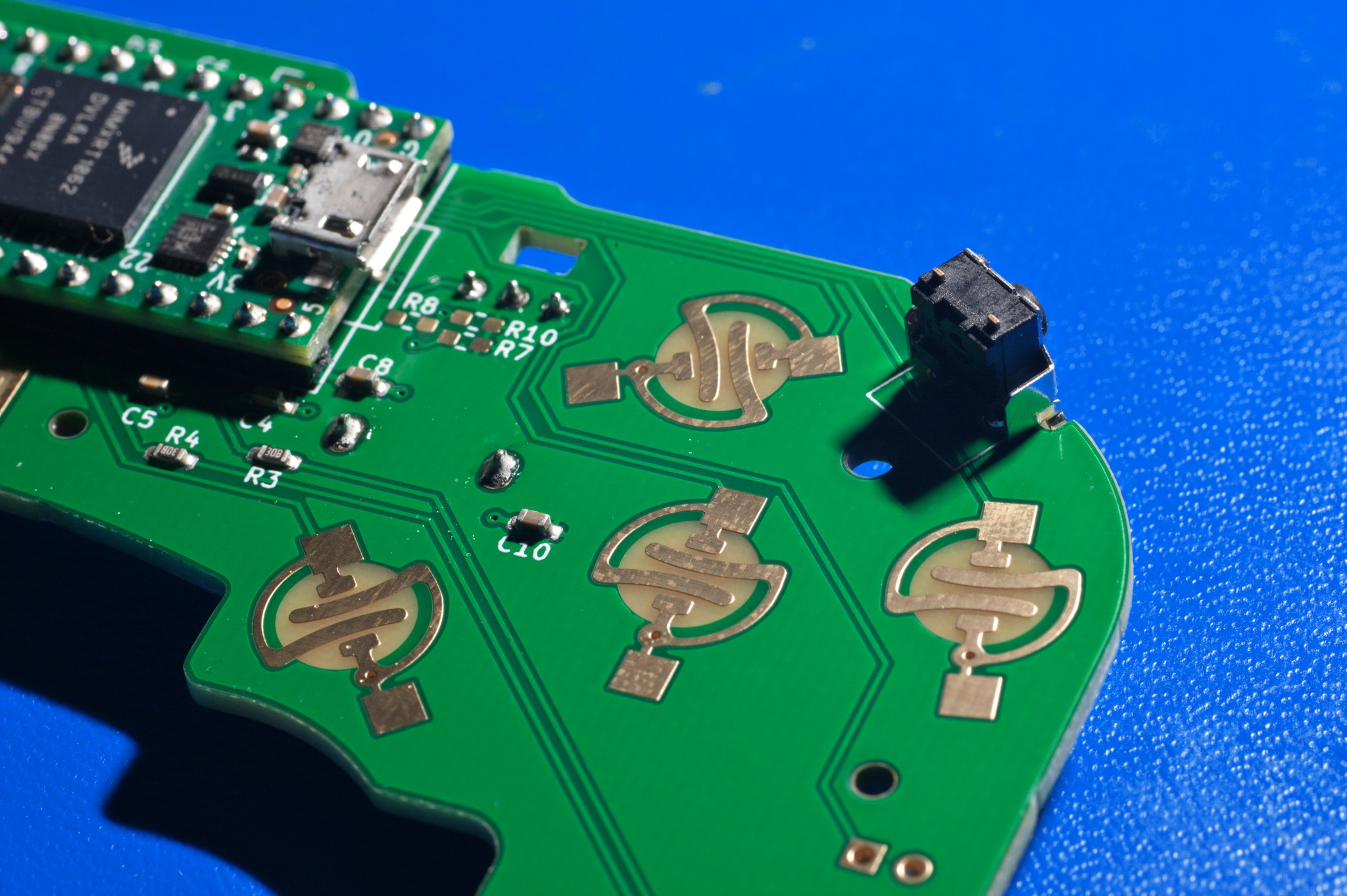
Solder it to the board, with extra solder applied to the contacts at the board edge. These are structural.
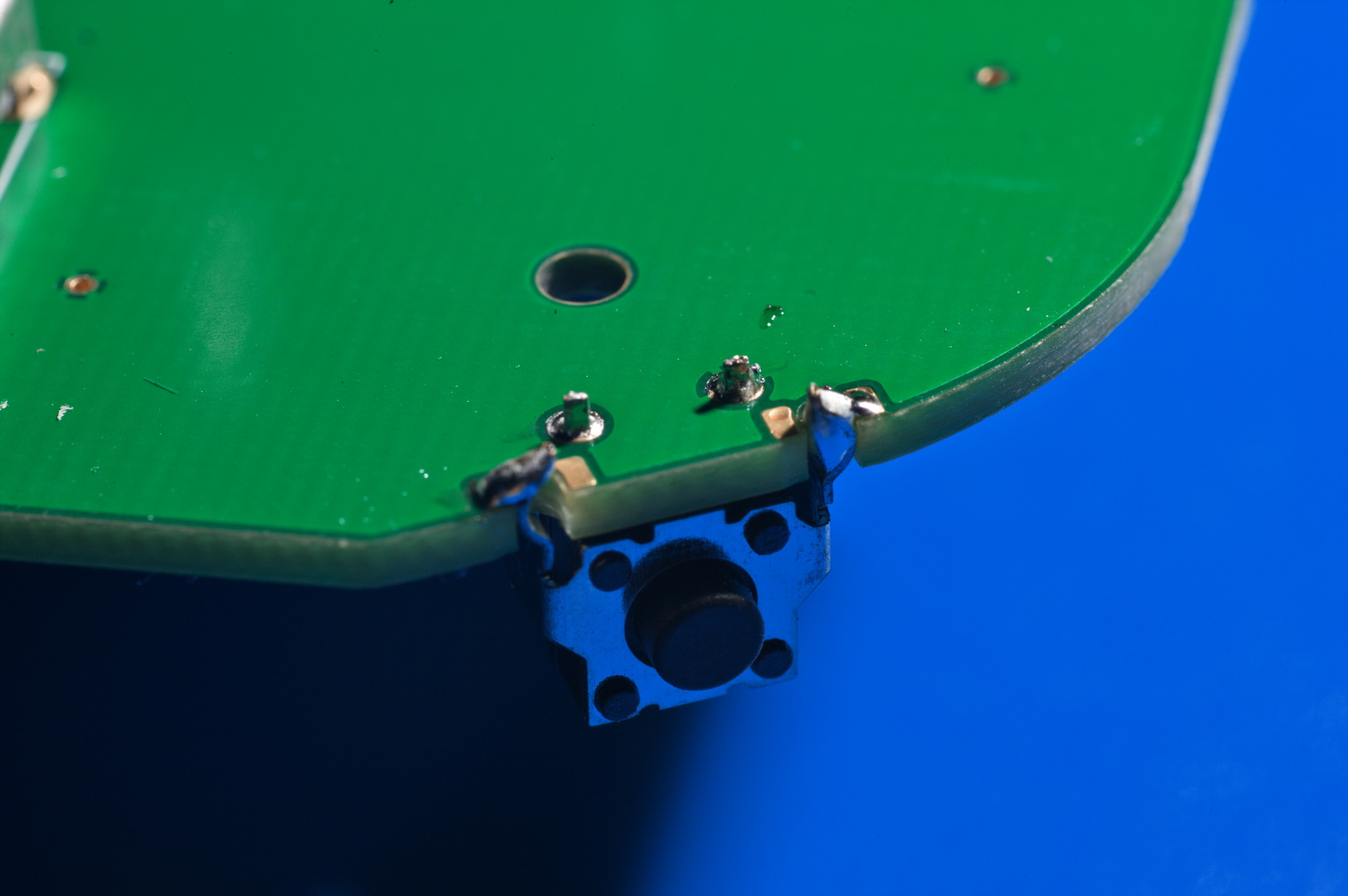
You do not need to solder the inner pads on the board edge.
OPTIONAL D-pad Buttons
This is an optional enhancement to the D-pad that goes underneath the OEM rubber domes.
This does not enhance the feel of the buttons, but it makes them harder to press accidentally and more consistent when you do want to press them. This is not suggested for Samus mains because it makes it harder to activate the Extended Grapple.
First, observe the wings on the button pads. The wings are where the switch contacts will go.
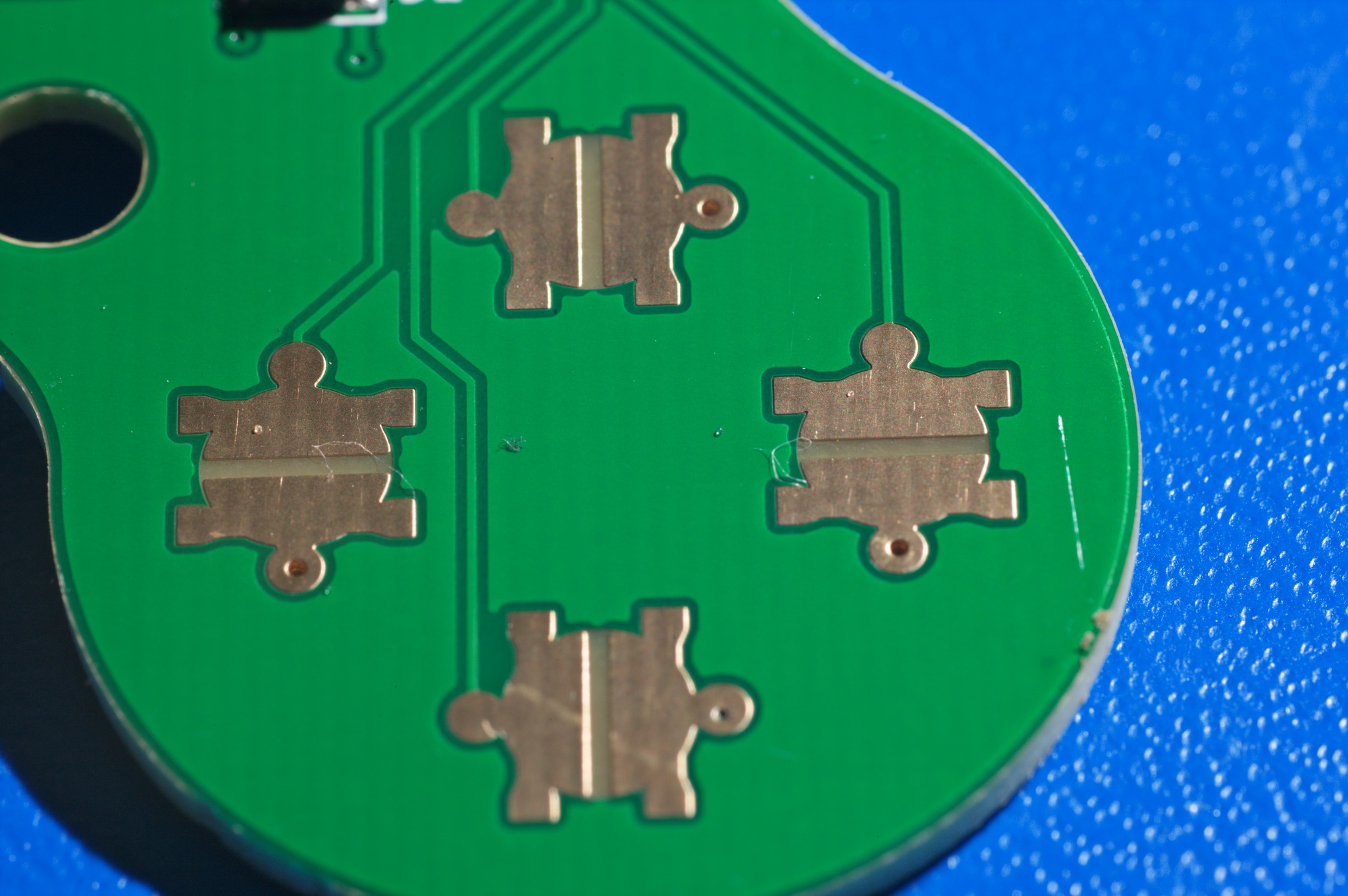
The switches on the right and left pads must be oriented with the contacts oriented horizontally, while the switches on the top and bottom pads must be oriented with the contacts oriented vertically.
If you mix this up, the buttons will be shorting the contacts all the time.
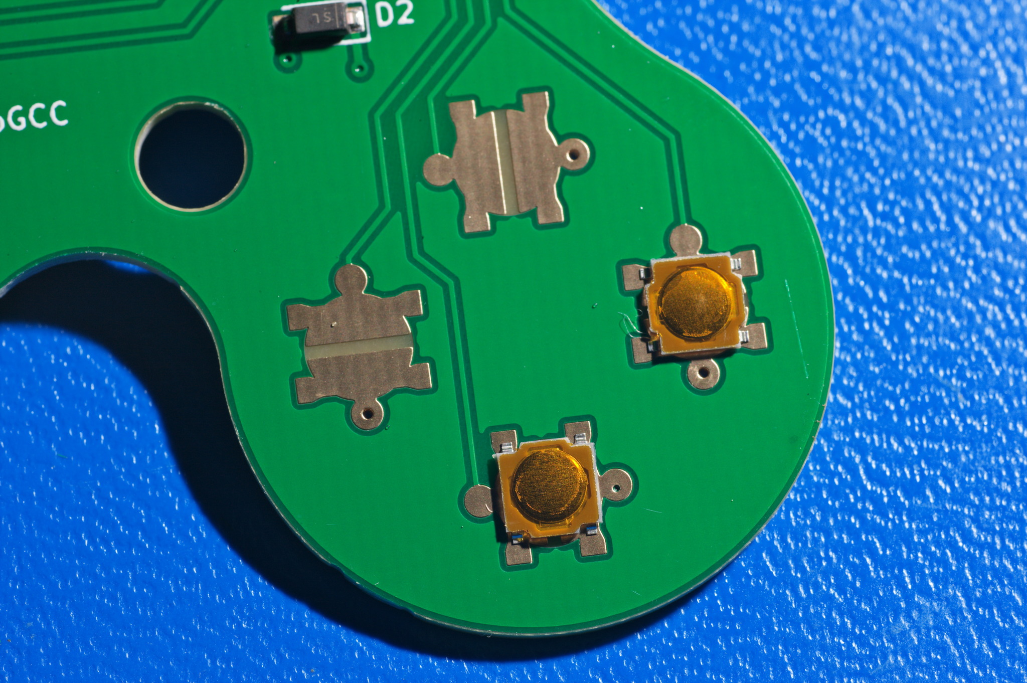
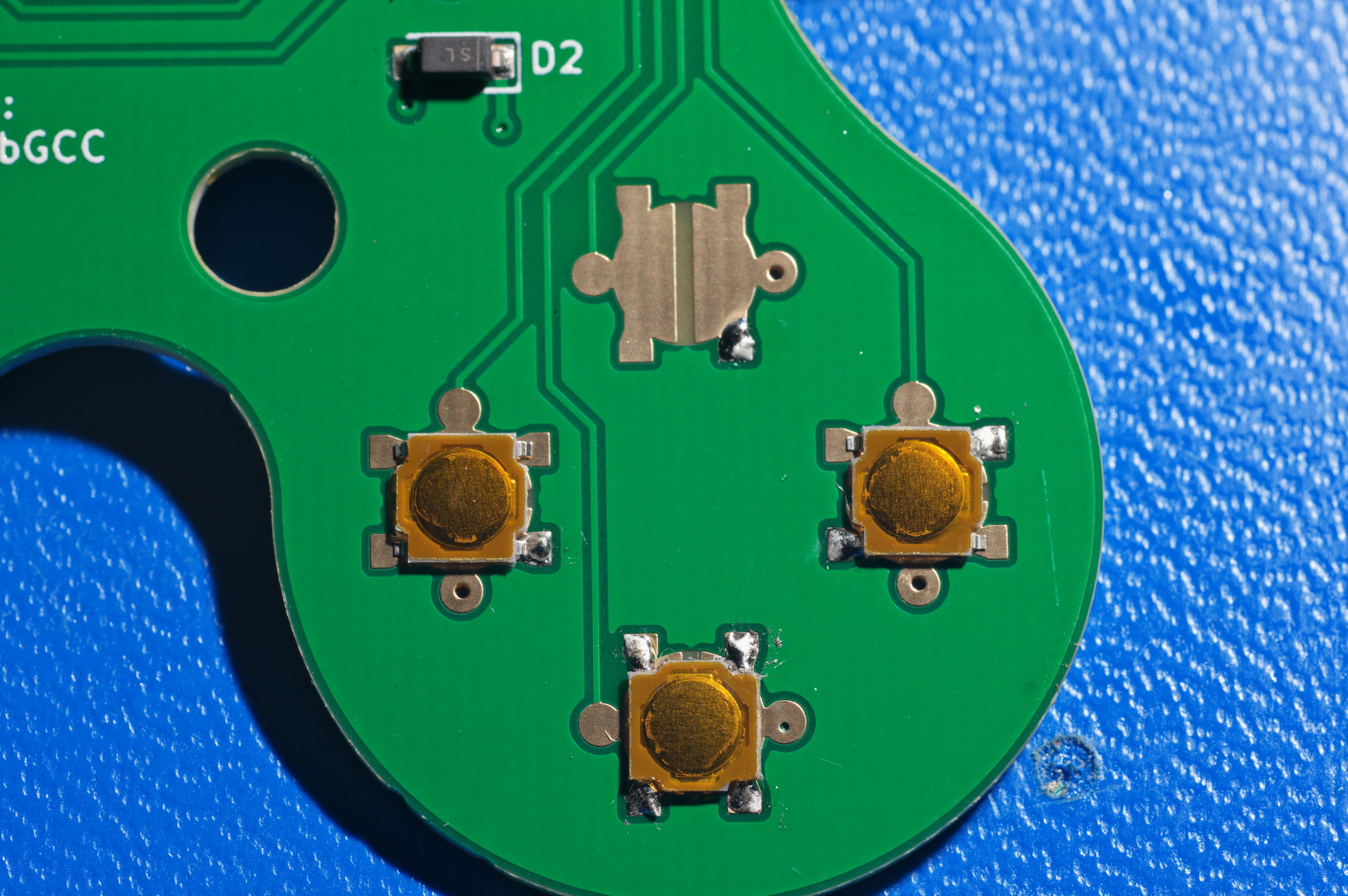
The process of soldering goes as shown:
Top: Apply a tiny bit of solder to one wing of the contact only.
Left: Using tweezers, hold a switch in place and melt the existing solder to tack it in place. Do all the buttons to this stage, then fit-check their placement using the shell to make sure they are centered under the rubber domes..
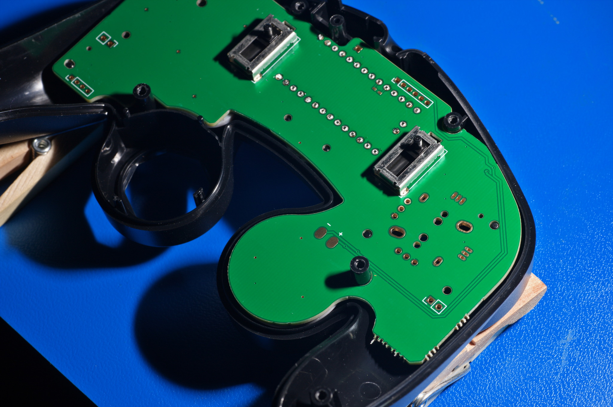
Right: Tack the opposite corner down using solder, then remelt the first corner and then this corner to eliminate strain.
Bottom: Solder down the rest of the corners.
The buttons should now look like this:
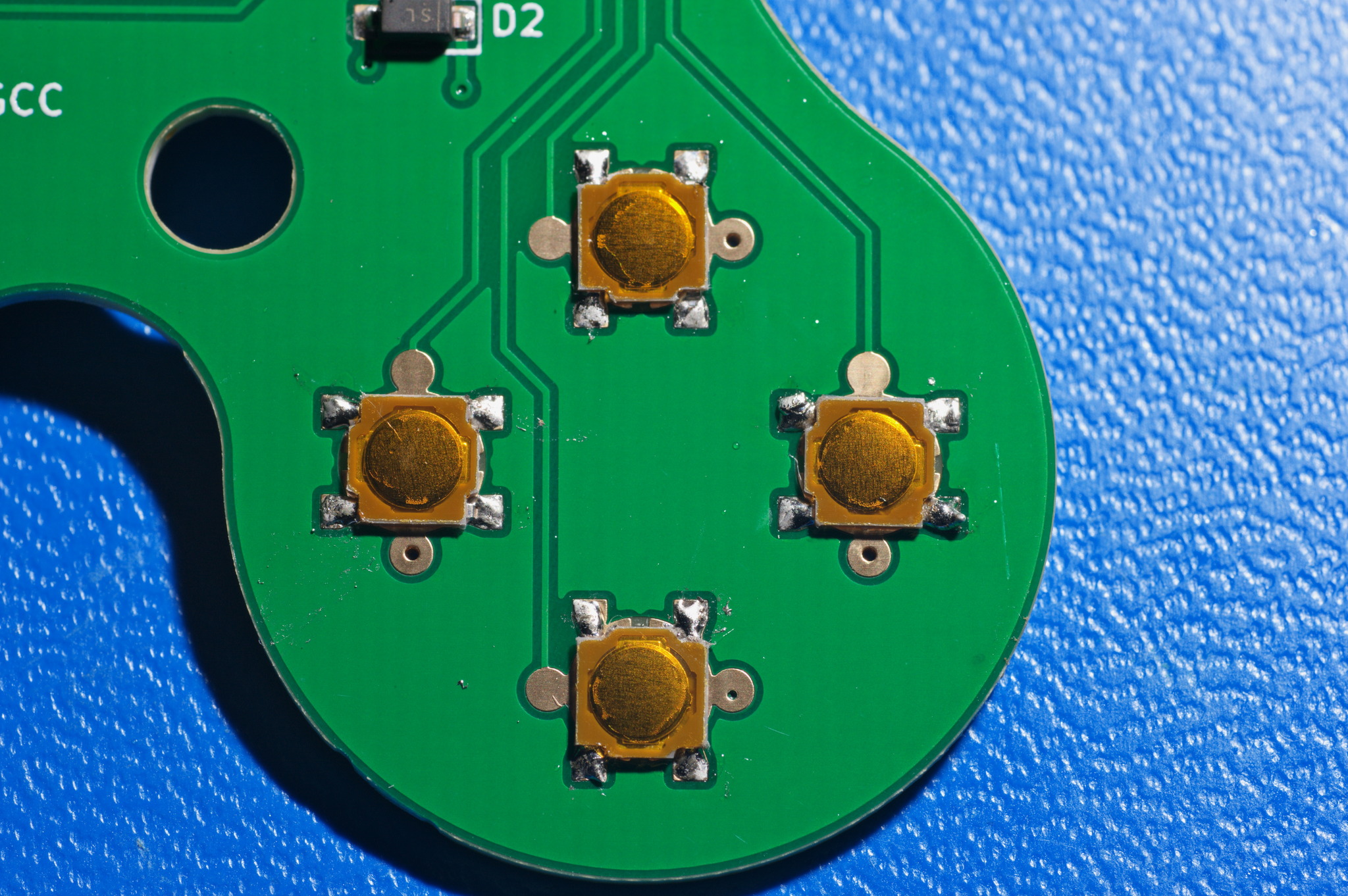
Using a multimeter, check continuity between the exposed copper pads that stick out past the button. They should be disconnected when the switch isn’t pressed, and shorted when the switch is pressed.
Bending and Soldering Hall Sensors
See this section of the PhobGCC 1.2 Assembly Video although it is missing the actual soldering. Also see the PhobGCC Hall Effect Sensor Soldering Video.
The Hall effect sensors come as a small black prism with two beveled edges.
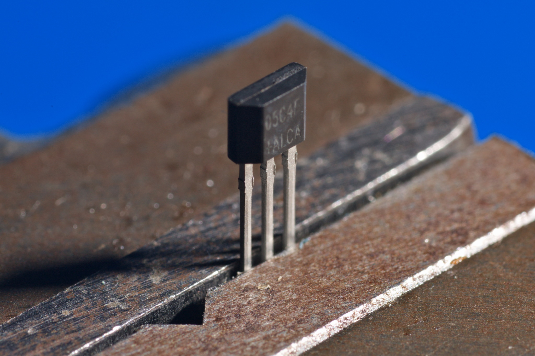
The legs of the Hall effect sensors must be bent 90 degrees so that the beveled edges face upward, with the bend as close as possible to the head of the sensor.
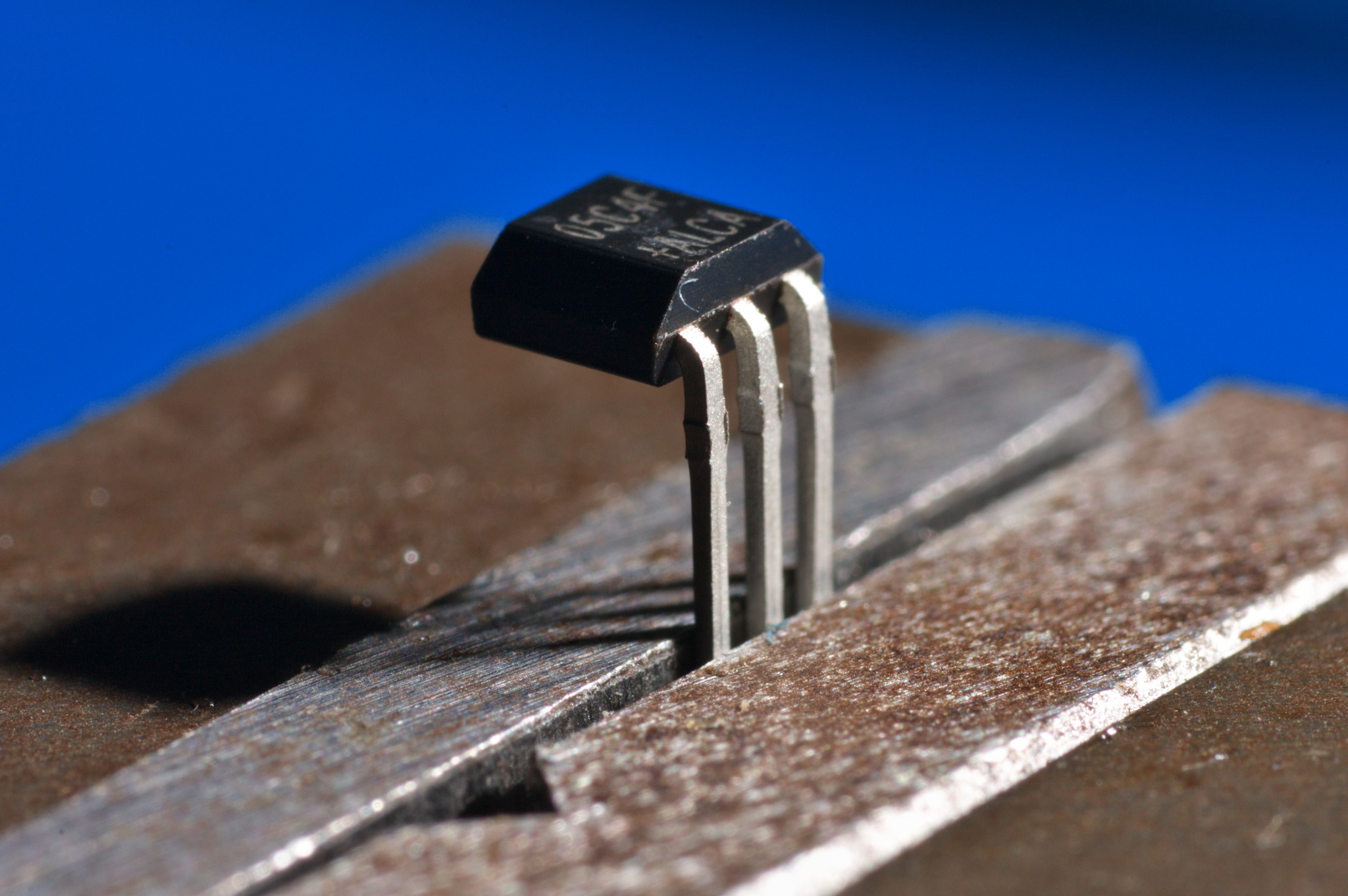
If the bends are located too far away from the body of the sensor, it will be difficult to get the stickbox in place.
Place the bent sensors in the board with the legs through the holes. Make sure they are on the upper side of the board with the text; this is easy to mix up on the C-stick board.
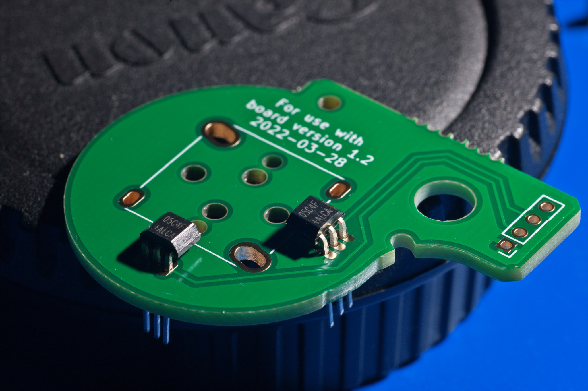
On the motherboard, place the Hall sensors on the top and left sides where the pads are small and close together. Do not try to spread the Hall sensor legs to fit through the wider-spaced holes on the bottom and right sides; you may break the sensor and it won’t work even if you manage to not break them.
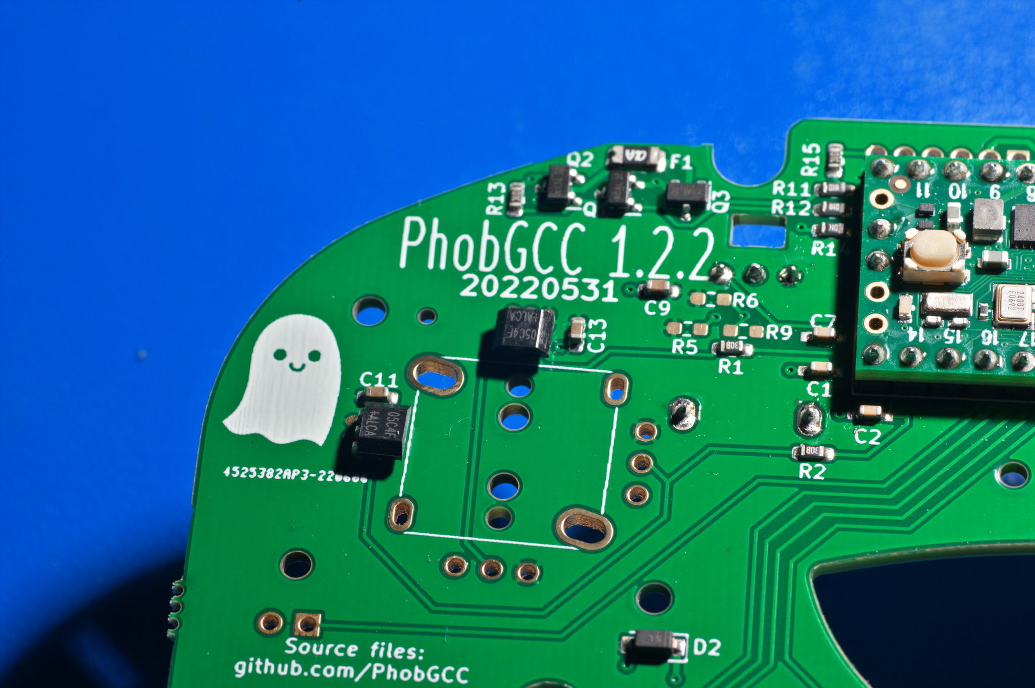
Install the stickboxes, already equipped with magnets, on the boards before soldering down the Hall sensors.
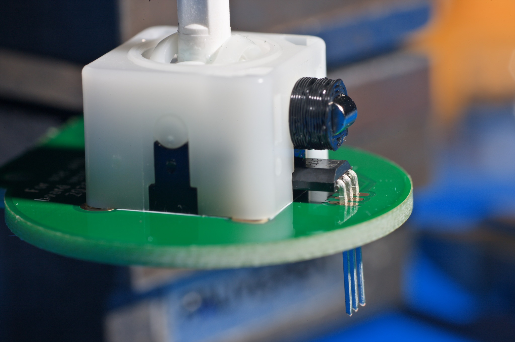
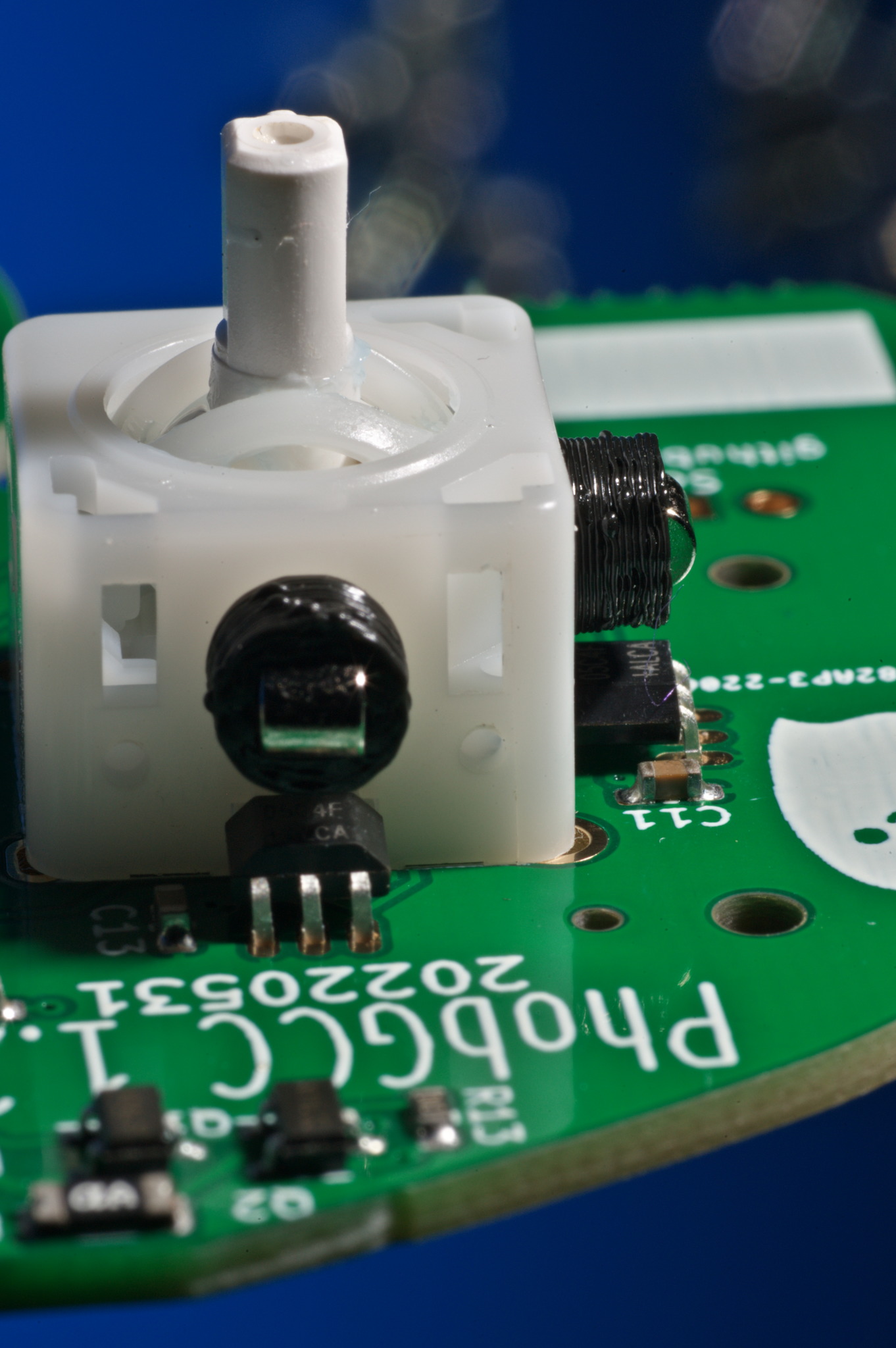
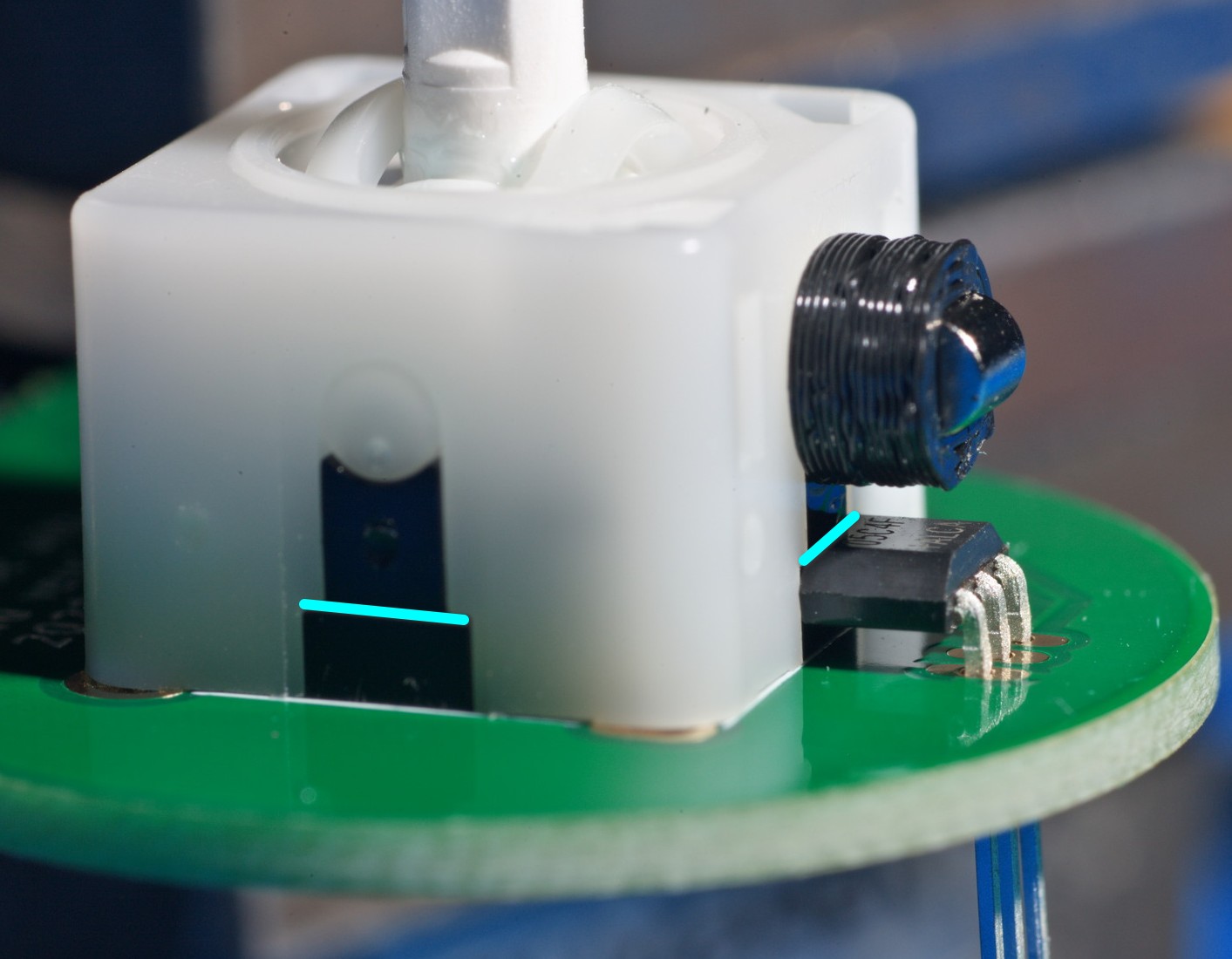
Align the height of the sensors to be roughly the level of this feature in the T3 stickbox or lower, making sure the sensors are centered and level. You may need to bend the legs a bit.
When you are satisfied with the sensor height, solder one leg in place. You can then use tweezers to manipulate the position while you remelt that one solder joint in order to fine-tune it.
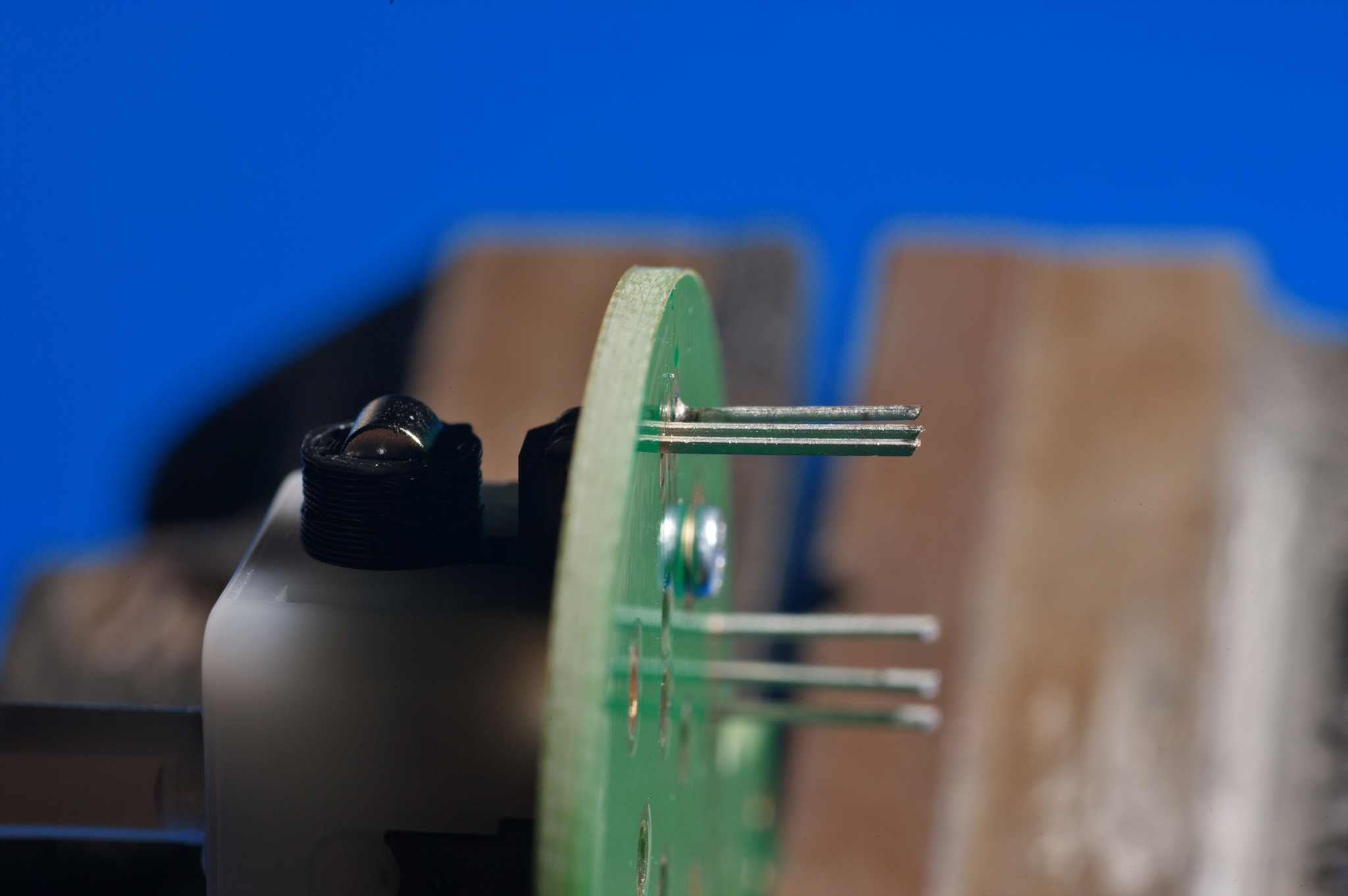
Then, solder the remainder of the legs.
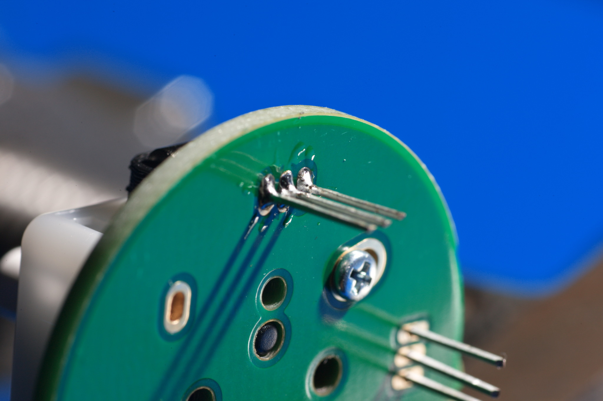
Finally, trim the legs.
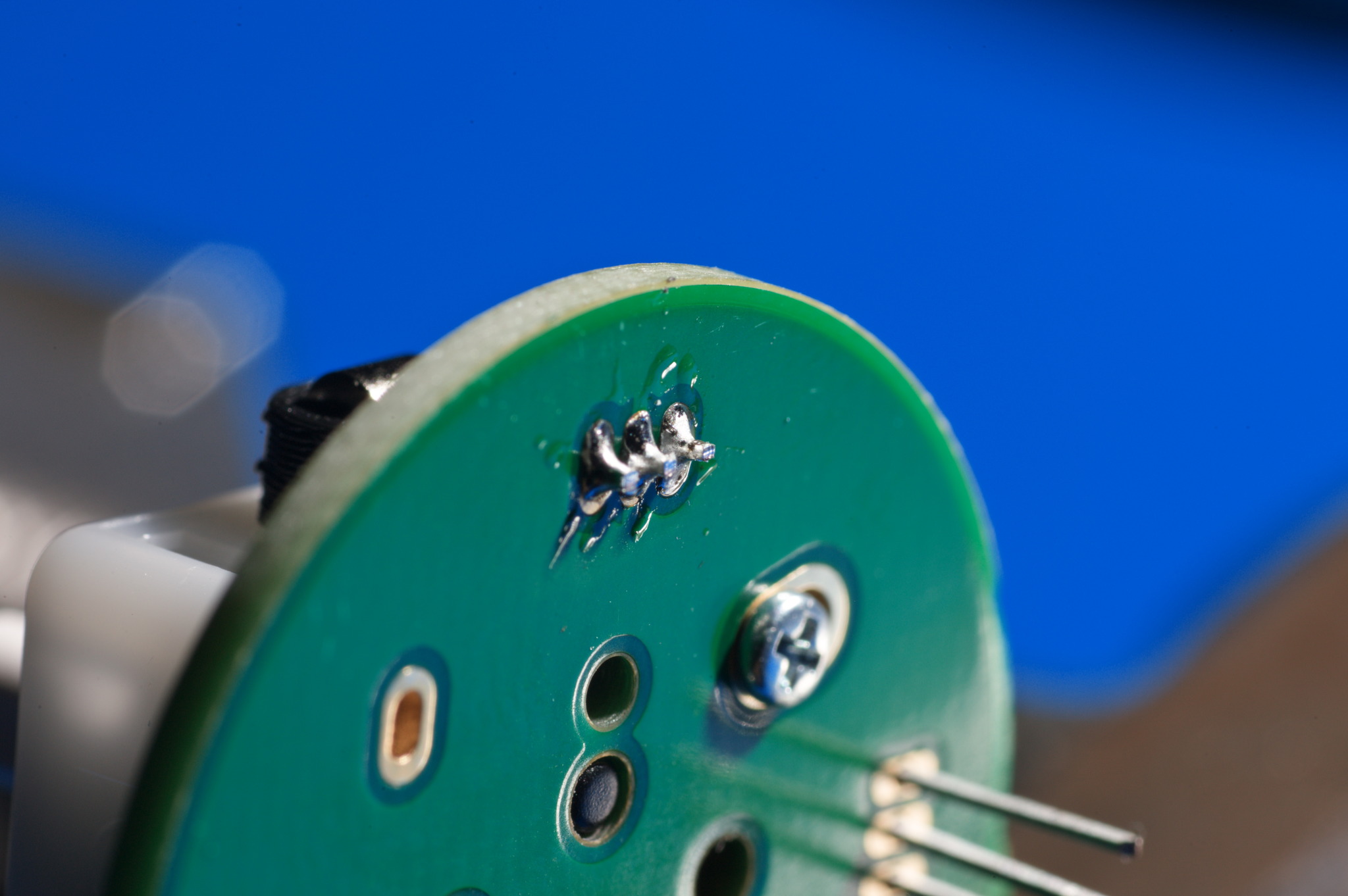
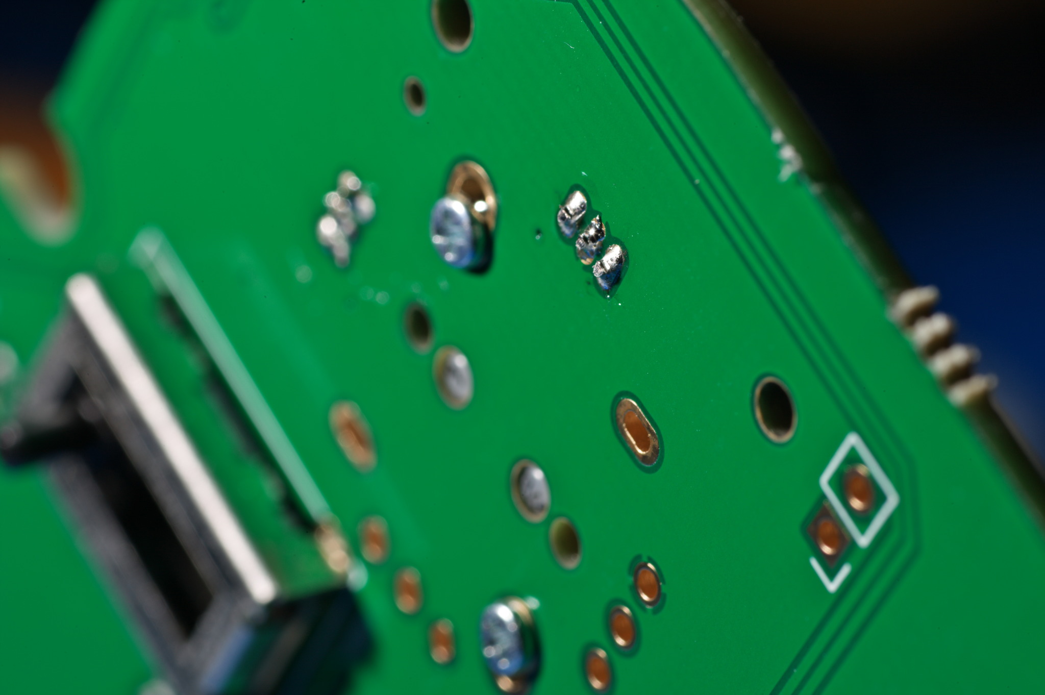
On the motherboard, trim the legs very closely and then reflow the solder on each joint. They should be no taller than half the height of the screw heads for the stickbox. If you don’t do this, it makes the controller harder to reassemble and may break the solder joints.
They do not need to be as flat on the C-stick.
Note: using leaded solder on the motherboard Hall effect sensors is a common cause of long-term failure for PhobGCC 1.2s. Leaded solder is soft and deforms easily when pressed upon by the trigger guard. This commonly causes a short-circuit, which does no damage but makes the analog stick hold hard left or hard right. Using SAC305 solder, which is harder, seems to have fewer issues. And as mentioned before, make sure that the Hall sensor solder joints are as flat to the board as you can make them, to help mitigate this issue.
C-stick Cable Soldering
See this section of the PhobGCC 1.2 Assembly Video.
You can either use the ribbon cable harvested from the OEM board, or you can solder in individual wires. If you use your own wires, have the insulation be about 3/4” (19mm) long.
Since I’m using the OEM cable, I prefer to put the red line on the side with the square pad on the C-stick board.
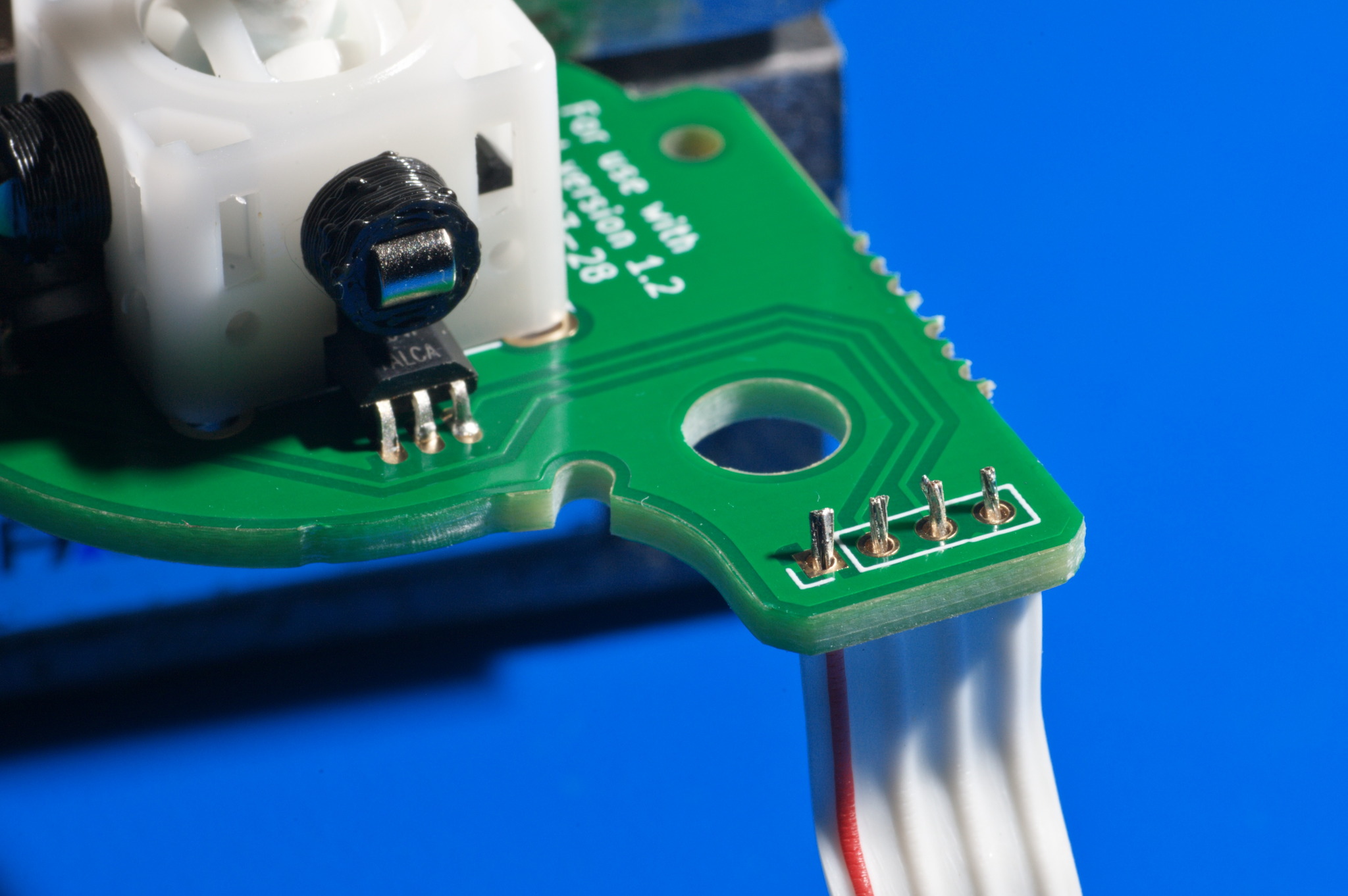
Solder the exposed ends to the pads.
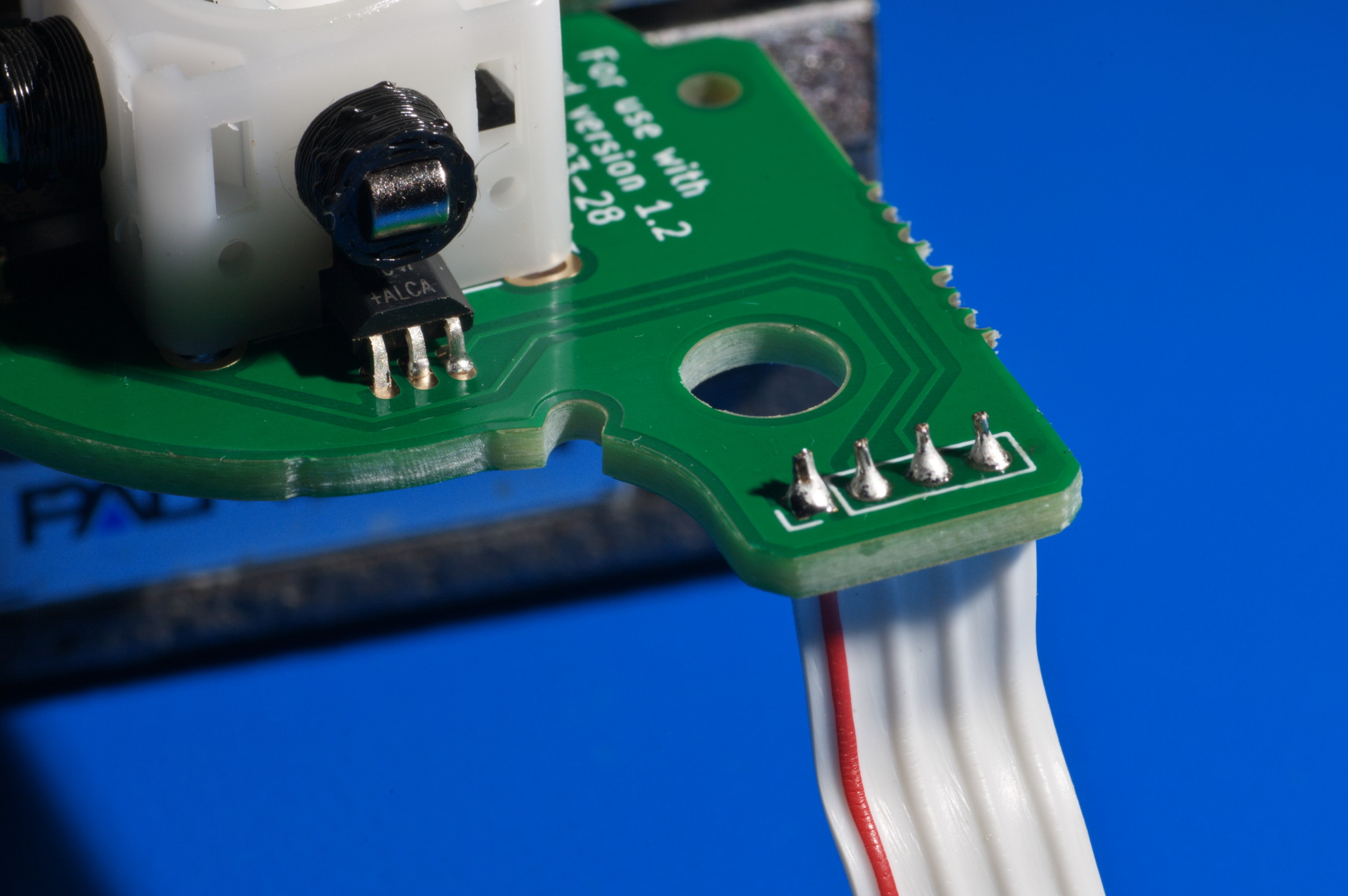
Next, connect the opposite end of either the ribbon cable or the wires to the motherboard. Make sure that both boards are facing up, and make sure they are oriented like this to ensure that the connections do not get mixed up.
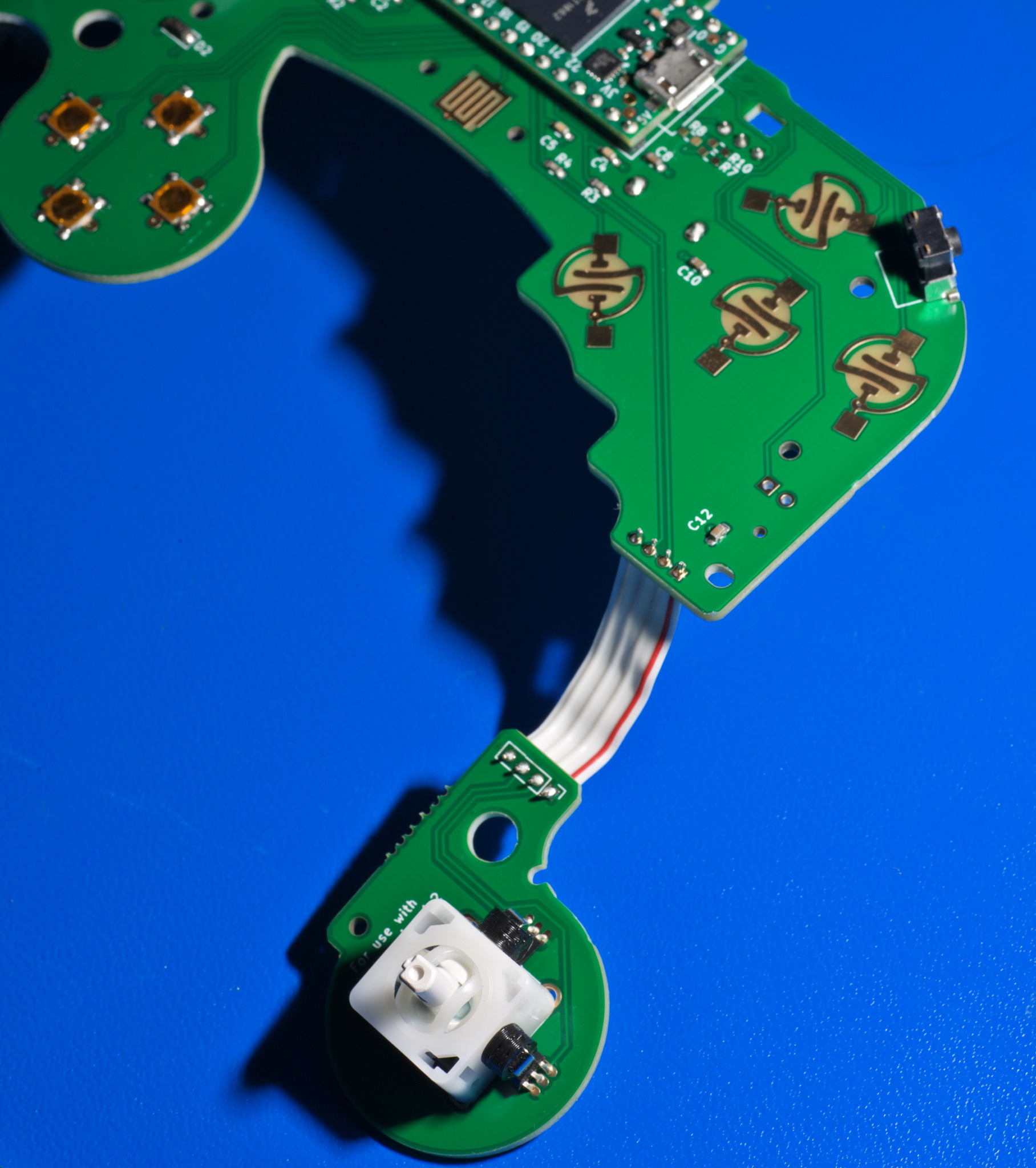
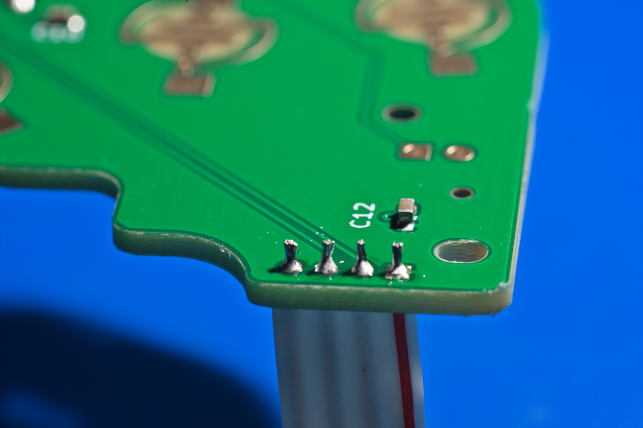
Then, solder the wires to the motherboard.
Controller Cable Soldering
See this section of the PhobGCC 1.2 Assembly Video.
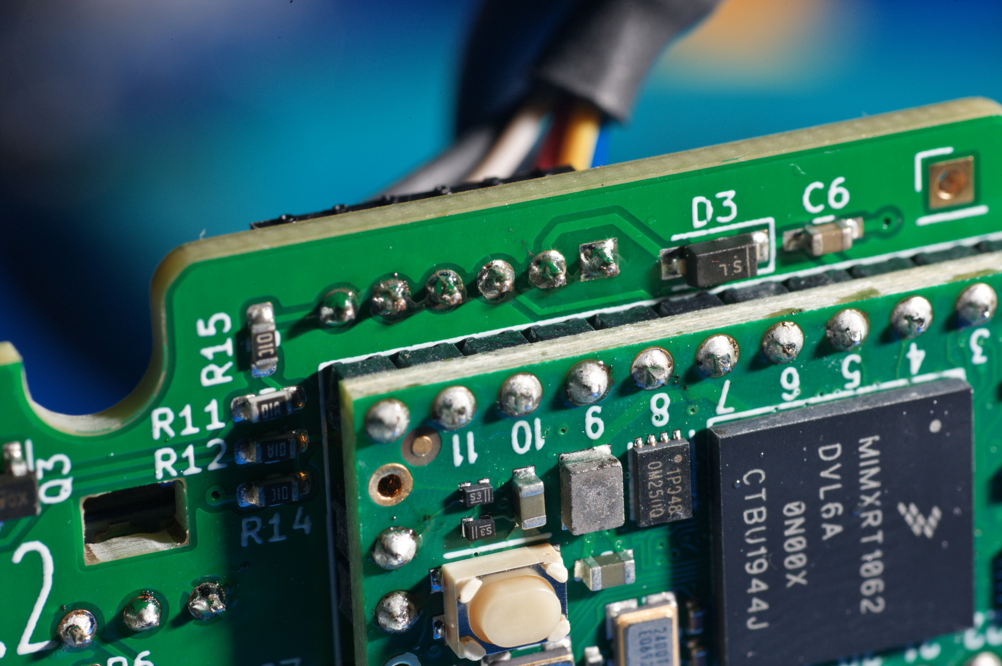
If you are using an OEM cable harvested from a first-party Gamecube controller, the black wire should be placed farthest from the center of the controller, and the blue wire closest to the center of the controller.
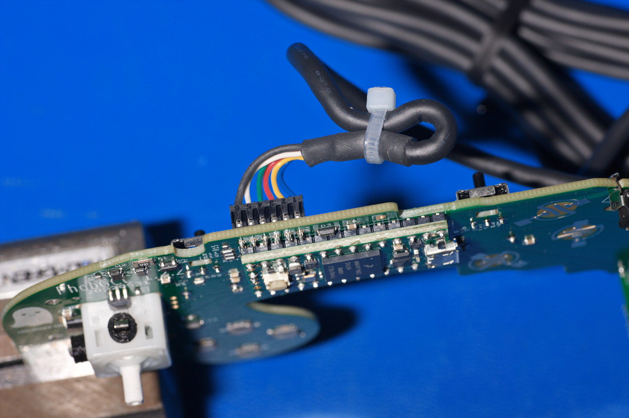
The pins themselves are actually basketlike sheet metal forms, so when you solder them, they take up a fairly large amount of solder.
Trigger Paddle Soldering
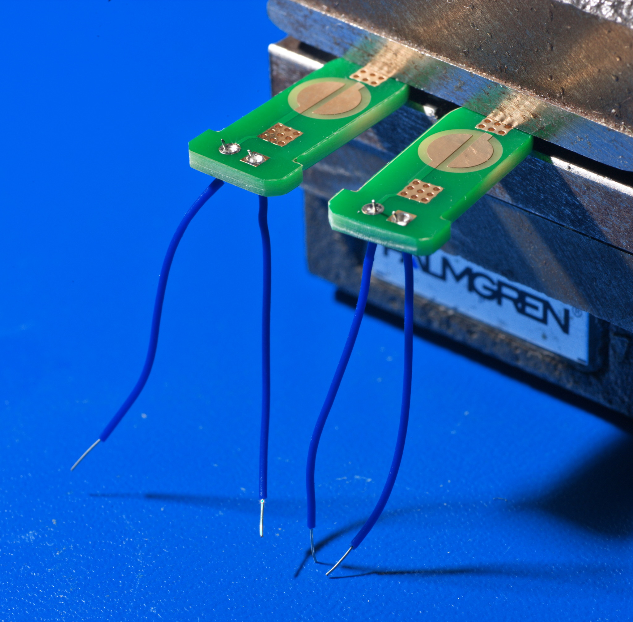
If you don’t harvest the trigger paddles from the OEM controller, you will need to prepare new wires for the PhobGCC’s trigger paddles.
It is possible to solder mouse buttons to these trigger paddles, but that is not covered here as it involves a more invasive modification to the OEM controller hardware.
Cut and strip wires that are roughly 1 inch long (25mm), and solder them in so that the wires are on the opposite side of the PCB from the pads.
Do not have the wires exit the front side with the contacts, or they can short to the Hall effect sensor pins.
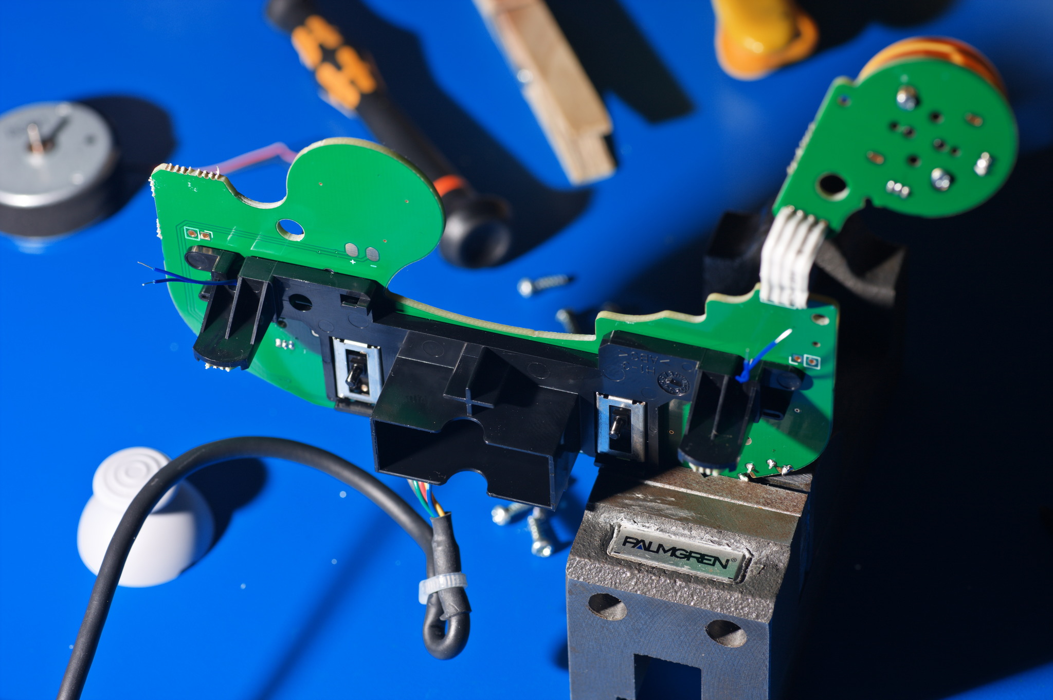
Load the trigger paddles with pads exposed into the rumble bracket (whether OEM or third-party), and mount the rumble bracket to the PCB. Make sure the wires safely exit the slots and do not get caught or pinched under the bracket.
Tuck the trigger paddle wires into the nearby holes in the motherboard.
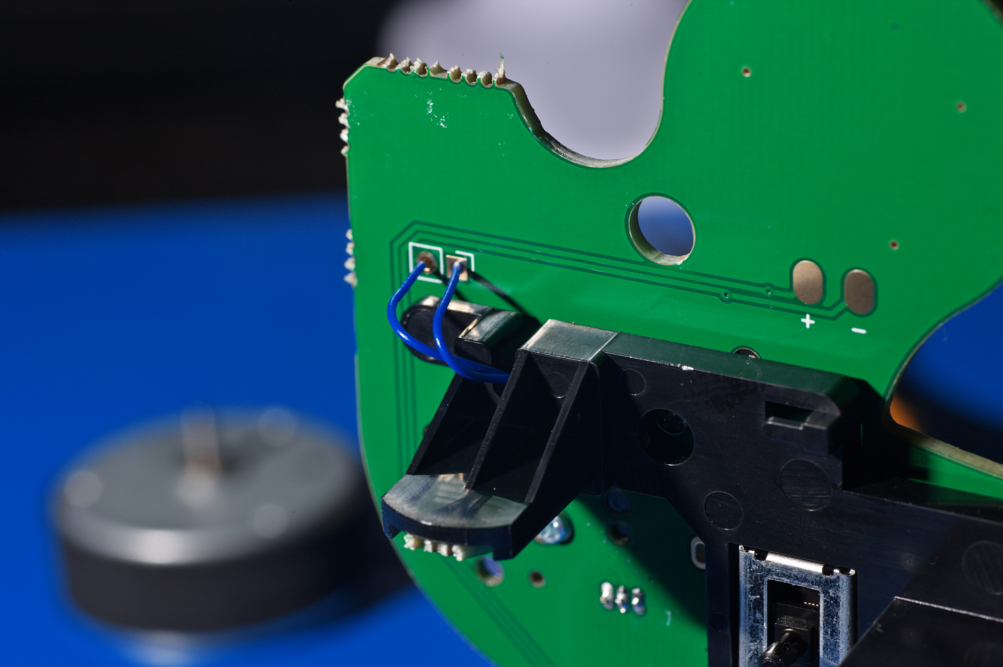
Then, being careful not to let them slip out, solder them to the motherboard.
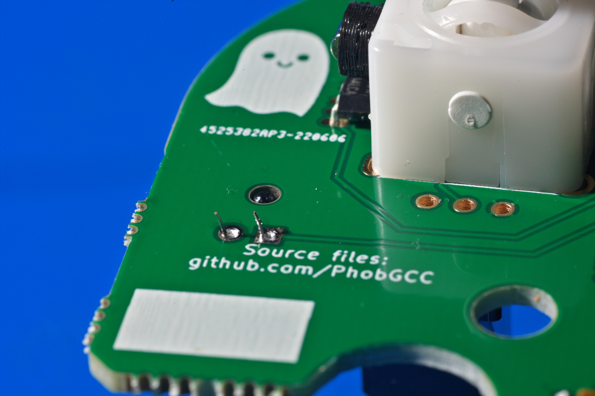
Rumble Motor Soldering
Next, mount the rumble motor back in the rumble bracket by inserting it into the rectangular box. Make sure that the shaft is on the cable side, and the motor is rotated so that the wires are on the D-pad side, close to the edge of the box.
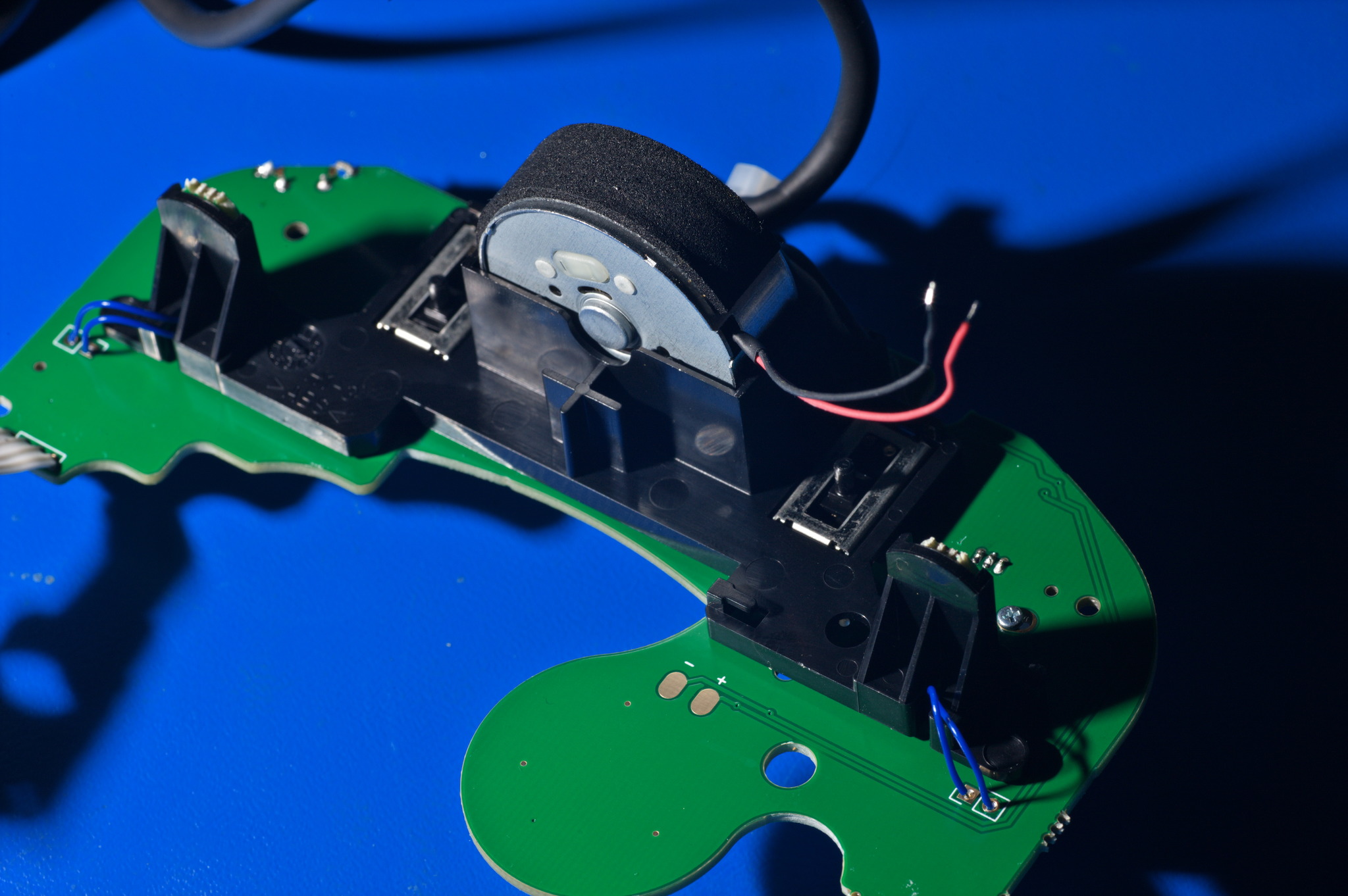
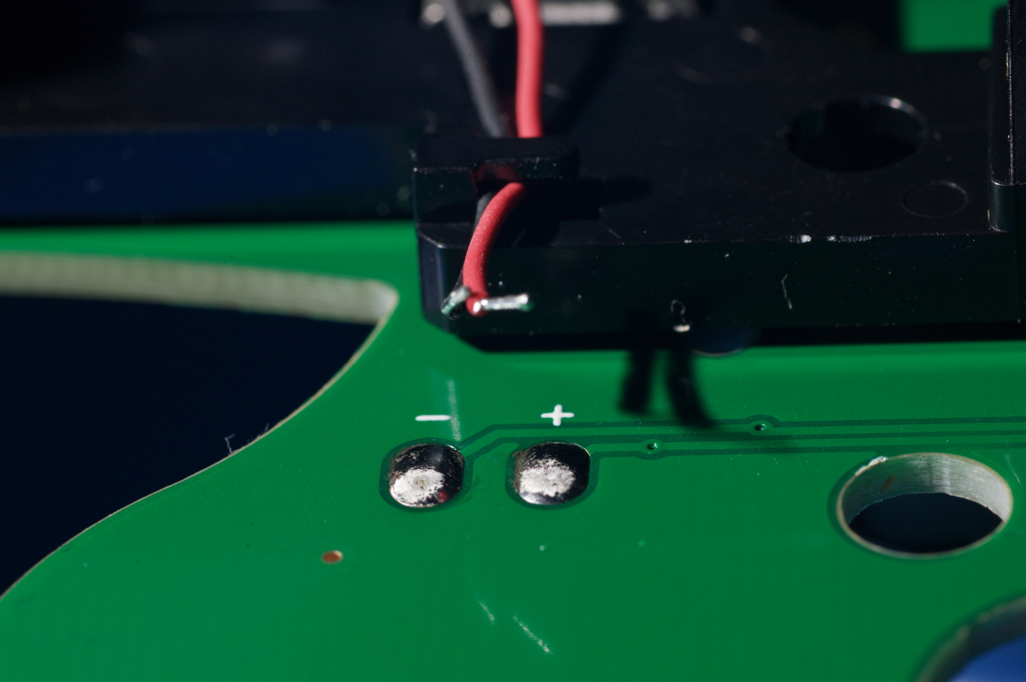
Apply a generous blob of solder to each of the rumble motor pads.
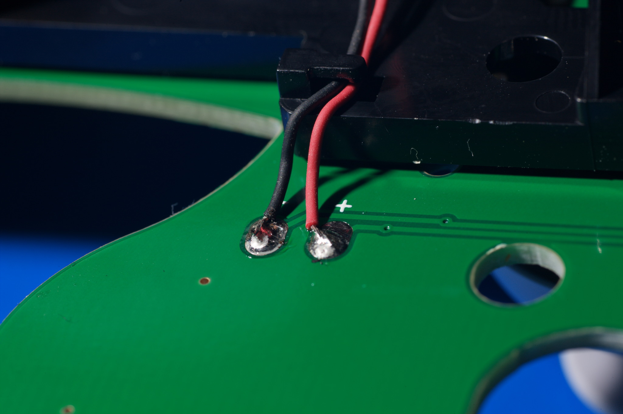
To solder the wires down, melt the blob of solder with your soldering iron and use tweezers to hold the wire in the pool. Remove the hot soldering iron, and keep the wire still as the solder cools.
Clip the wires into place on the rumble bracket.
Completion and next steps
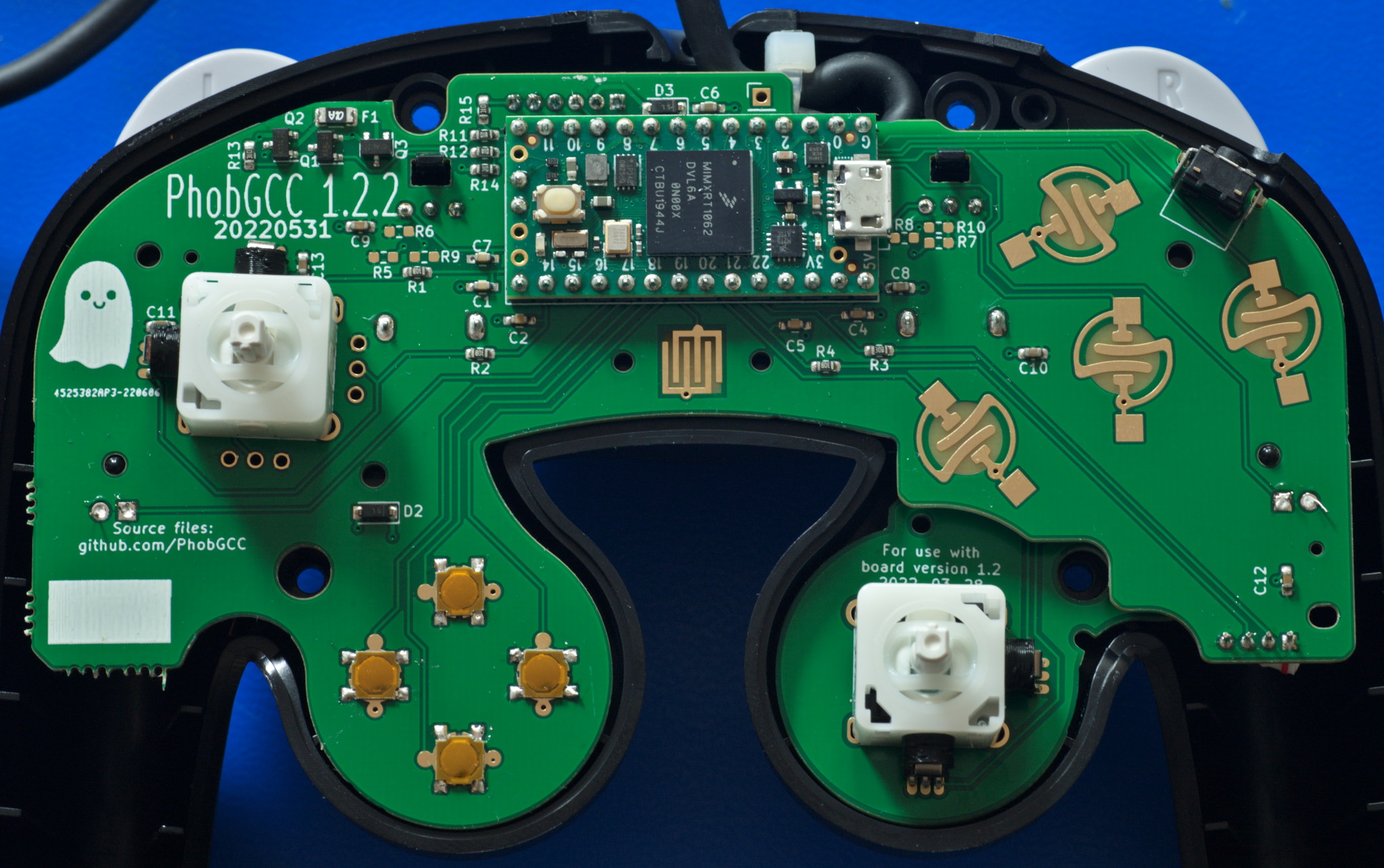
Now that you have completed the soldering steps, follow the Board Debugging Guide for PhobGCC 1.2 to make sure it’s ready to go.
Then, reassemble it, and follow the Initial Steps in the PhobGCC Calibration Guide for the version of the software you have flashed on the Teensy.
And, enjoy!
 This work is licensed under a Creative Commons Attribution-ShareAlike 4.0 International License.