PhobGCC 2.0 Build Guide
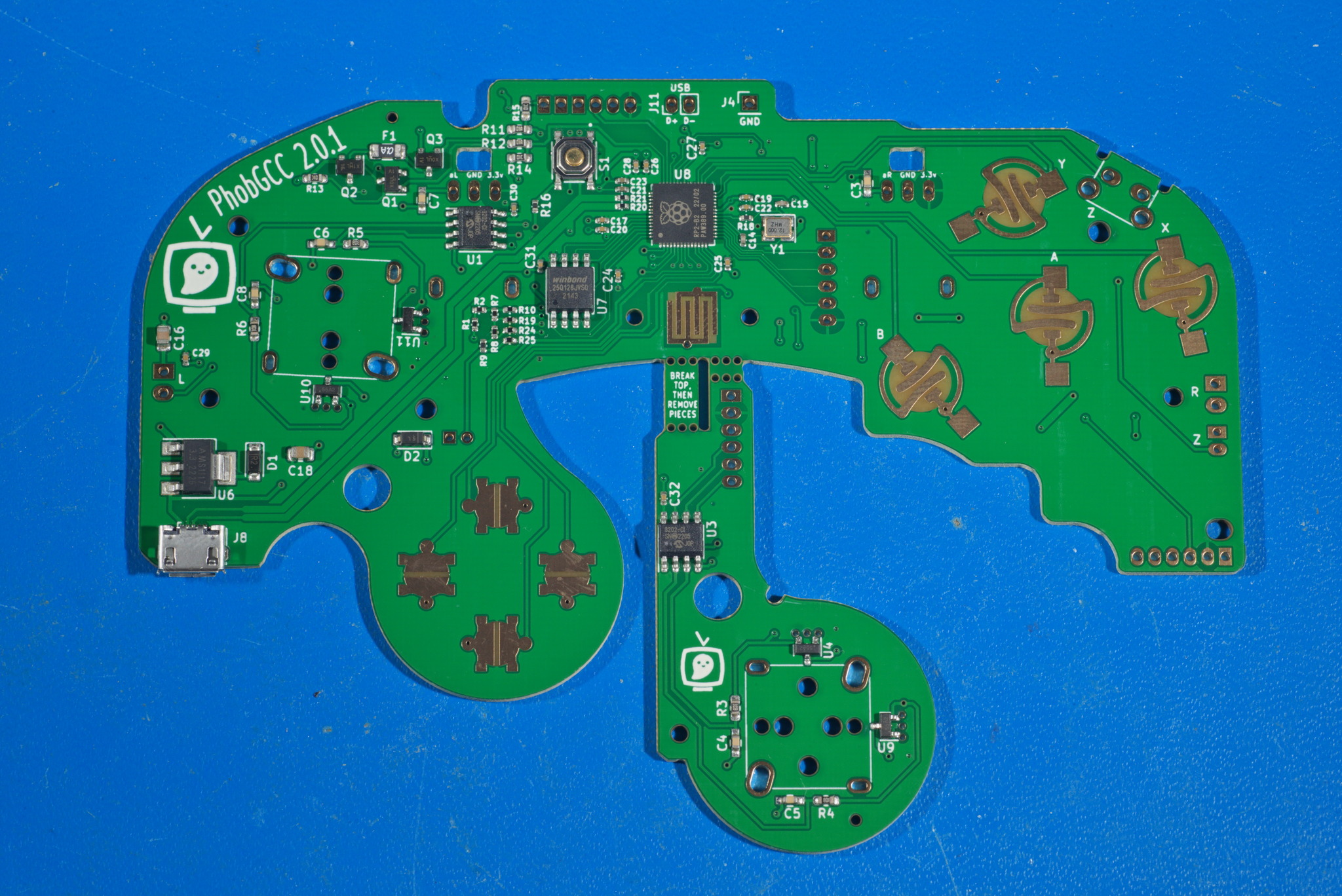
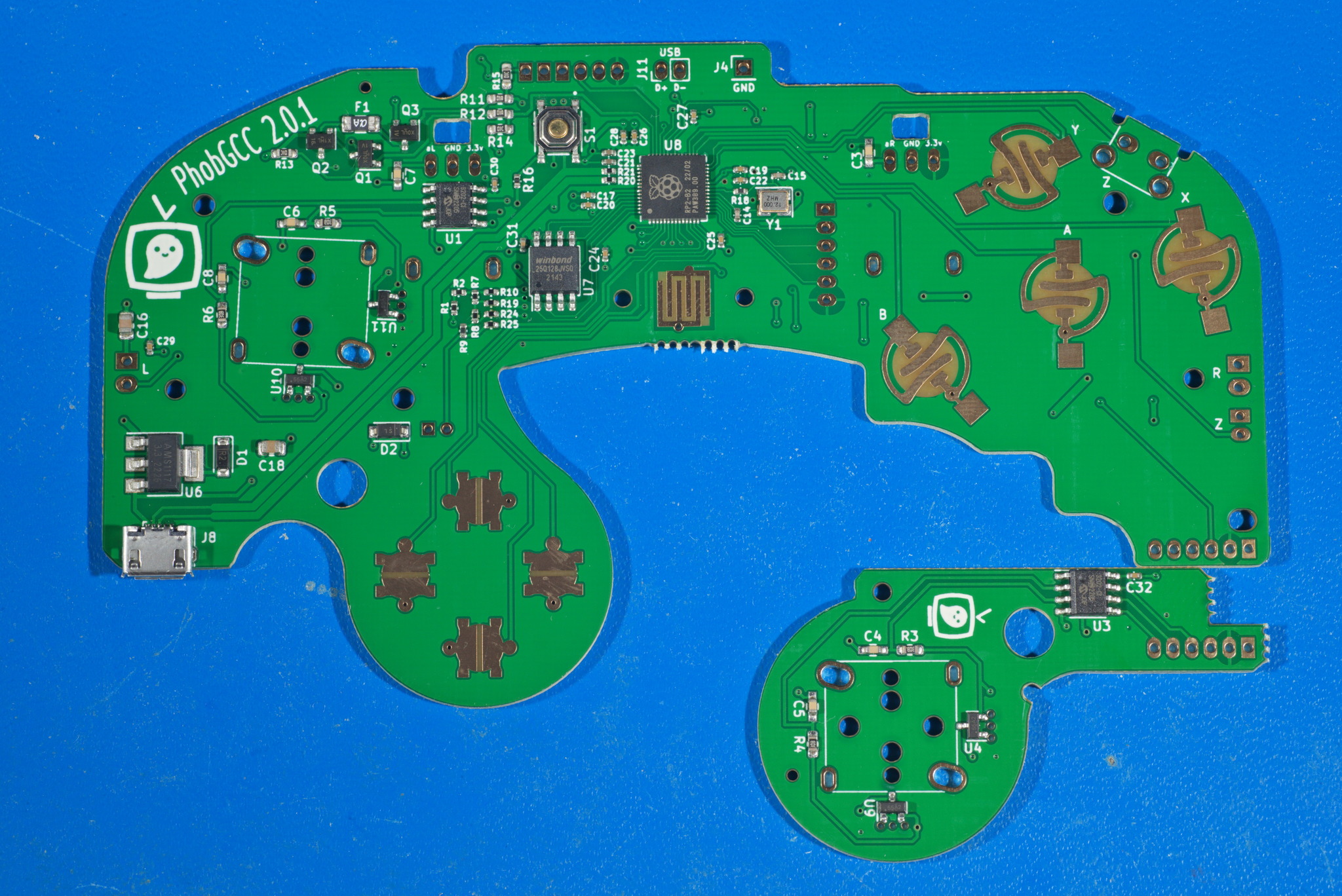
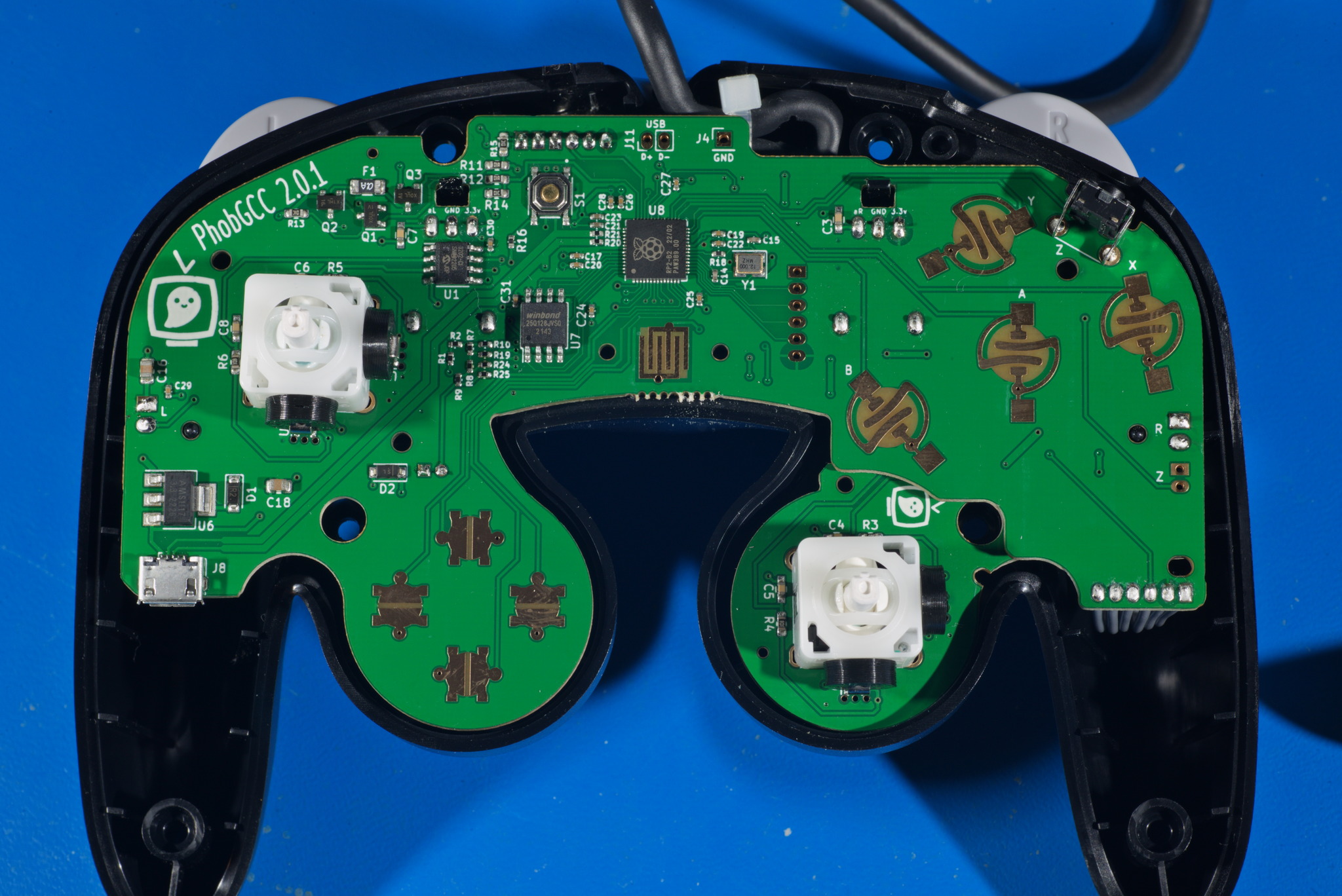
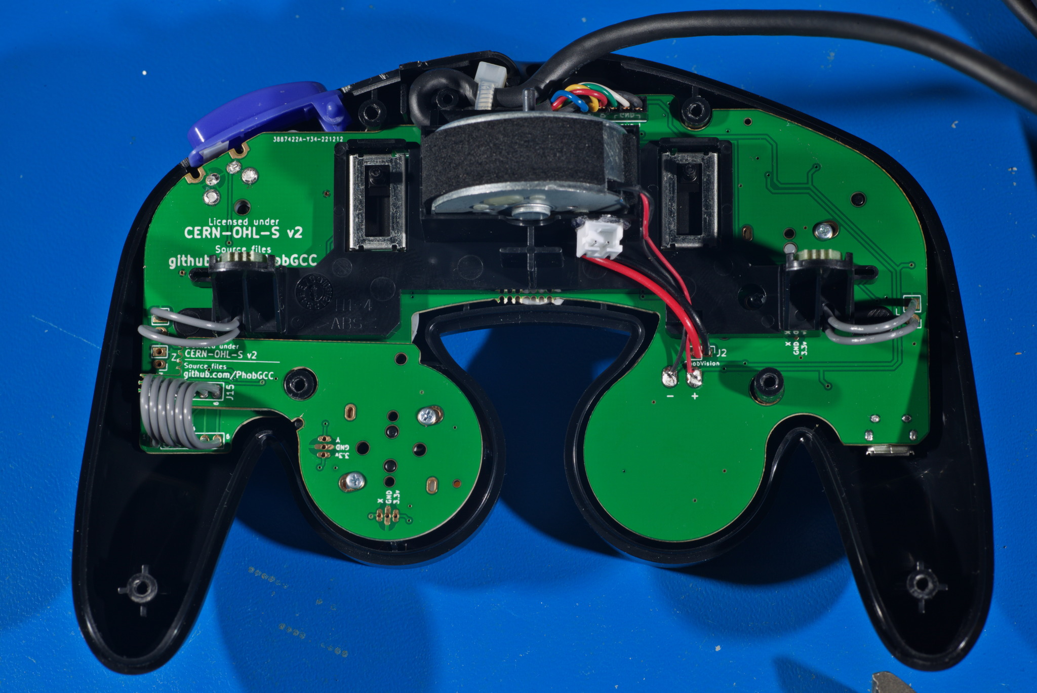
This is an illustrated guide to making a PhobGCC 2.0, using photos taken of a PhobGCC board version 2.0.1.
Newer board versions may differ slightly in appearance but this guide will still be applicable.
If you want to see it in motion, watch the PhobGCC 2.0 Assembly Video.
Unlike previous releases, PhobGCC v2.0 is much more beginner friendly and if you follow the instructions precisely it is possible to build a PhobGCC as your very first soldering project.
It is still recommended to get a soldering practice kit to build your physical understanding of the soldering process with before you start.
And make sure to follow every single step without fail, because there’s many ways to make the controller nonfunctional.
Tools
It’s possible to work with cheap tools and supplies if you’re very skilled.
But if you cheap out on solder or soldering iron “because you’re just a beginner” you will be in for a lot of pain and suffering.
Come to the PhobGCC Discord Server for advice on what to get if you’re at all unsure.
Required Tools
- Temperature-controlled soldering iron with a moderate size chisel tip. DO NOT USE AN UNCONTROLLED TEMPERATURE IRON!
- Flux-core solder, ideally no-clean flux (Sn63Pb37 melts at a lower temperature, SAC305 is nontoxic and flows better)
- No-clean rosin flux paste (not to be confused with solder paste)
- Tri-Wing screwdriver and small JIS driver set (Phillips drivers can strip screws)
- Sharp tweezers
- Solder sucker (or more sophisticated desoldering tool)
- Vise or PCB support (the alligator clip kind is not very useful)
- Multimeter for debugging
- 90%+ rubbing alcohol and cotton swabs
Suggested Tools
- Anti-static mat/grounding strap
- Fume fan
Parts
Some of the parts are taken from a donor Gamecube controller, while others must be sourced new. Check the PhobGCC Ordering Guide for a list of what you need to purchase.
New Parts
- PhobGCC v2.0.0 board (includes C-stick board)
- 4x magnets
- 3D-printed magnet holders and superglue
- Optional 2x trigger paddles
- Optional 4x D-pad buttons
- Optional 4x mouse buttons for ABXY (assembly not depicted)
- Optional 1x or 2x mouse buttons for triggers (assembly not depicted)
- Wire
Internal Parts Harvested from Donor GCC
Not counting the shell, buttons, stick caps, etc.
- 2x Stickboxes
- 2x Trigger potentiometers
- Cable (or make or buy your own)
- Rumble Motor (or use a cellphone rumble)
- Rumble Bracket (or source your own 3D-printed one)
- Z-button switch
- Optional trigger paddles with attached wires
Build Process
GCC Part Harvesting
Begin by taking apart the donor GCC using a Tri-Wing screwdriver.
Remove the motherboard.
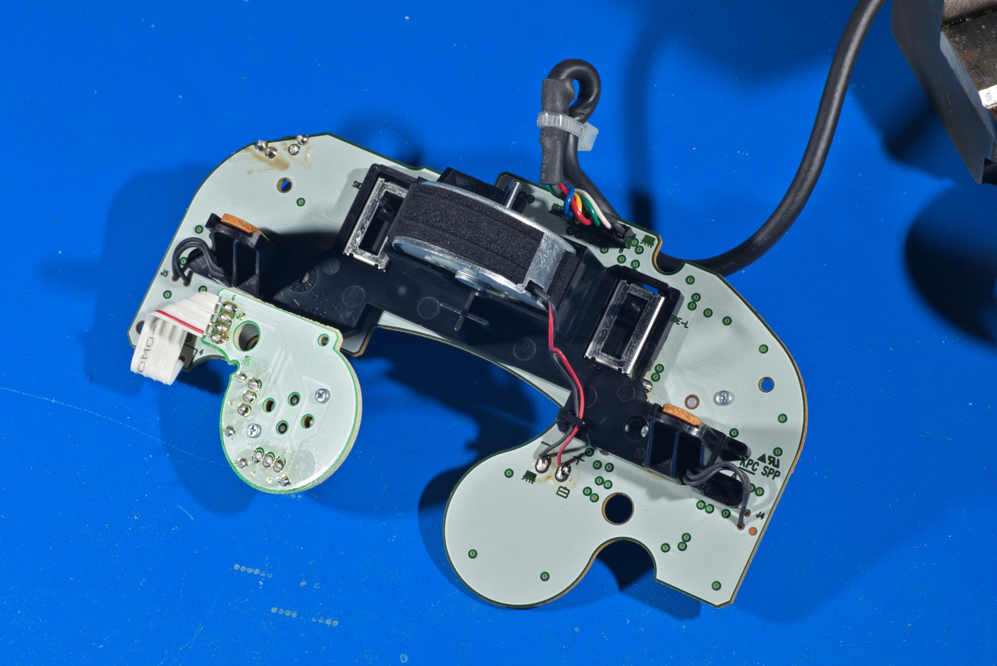
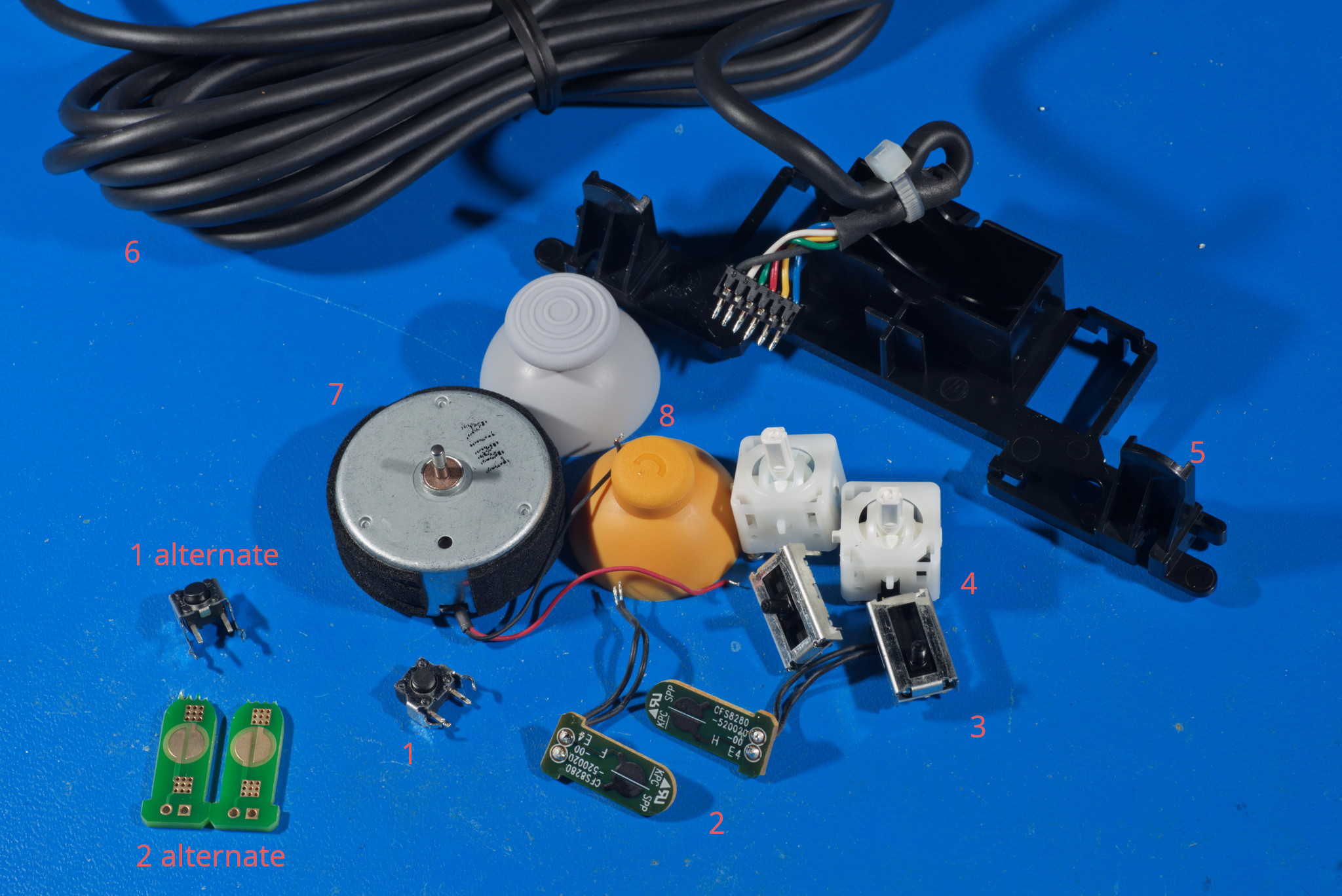
You will want to remove the following parts from it:
- Z button (or supply your own alternate as shown)
- Trigger paddles (or use PhobGCC ones as alternates as shown)
- Trigger potentiometers
- Stickboxes (preferably T3)
- Rumble bracket (or supply your own 3D-printed one)
- GCC cable (or supply your own)
- Rumble motor (or omit it, or use a cell rumble)
- Stick caps
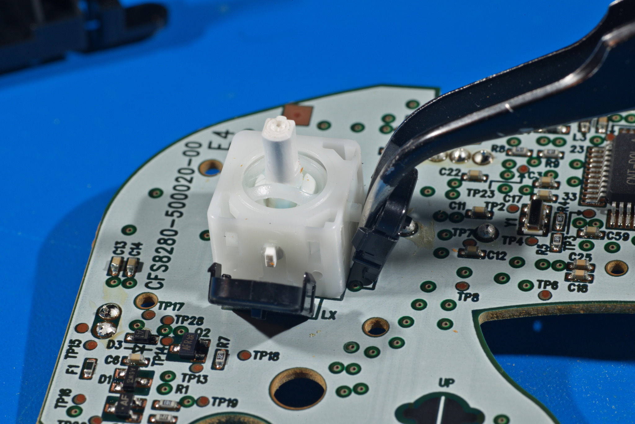
If you’re not familiar with removing the stickboxes, you can stick the points of tweezers between the stickbox and the potentiometers to unclip the potentiometers. Then, use a JIS #0 screwdriver to unscrew the screws from the bottom of the stickboxes.
Critical Step: Magnet Mounting
PhobGCC 2 uses sensors mounted perfectly flat on the board, which was not recommended for PhobGCC 1. If you were to glue magnets to the peg or use centered magnet holders designed for PhobGCC 1, the signal would be much too weak and the nonlinearities would be undesirable.
Therefore, for PhobGCC 2.0 we are making 3D-printed magnet holders mandatory. You can get an adjustable parametric OpenSCAD file in the pins of the 3d-printing channel on the discord, or you can get magnet holder STLs designed for use with JLCPCB in the PhobGCC 2 hardware releases.
When using 3D-printed magnet holders, we strongly urge you to superglue (cyanoacrylate) the holders to the stickbox pegs. It’s easiest to do this early in the process so that the superglue cures sufficiently before you need to install the stickboxes.
First, clean the grease off the stickbox pegs with isopropyl alcohol and wipe off the alcohol. Do not allow it to evaporate on its own, or it will simply redeposit the grease back down.
Then, I prefer to scratch up the pegs using a steel pick or a razor blade. This exposes clean, fresh plastic for gluing to.
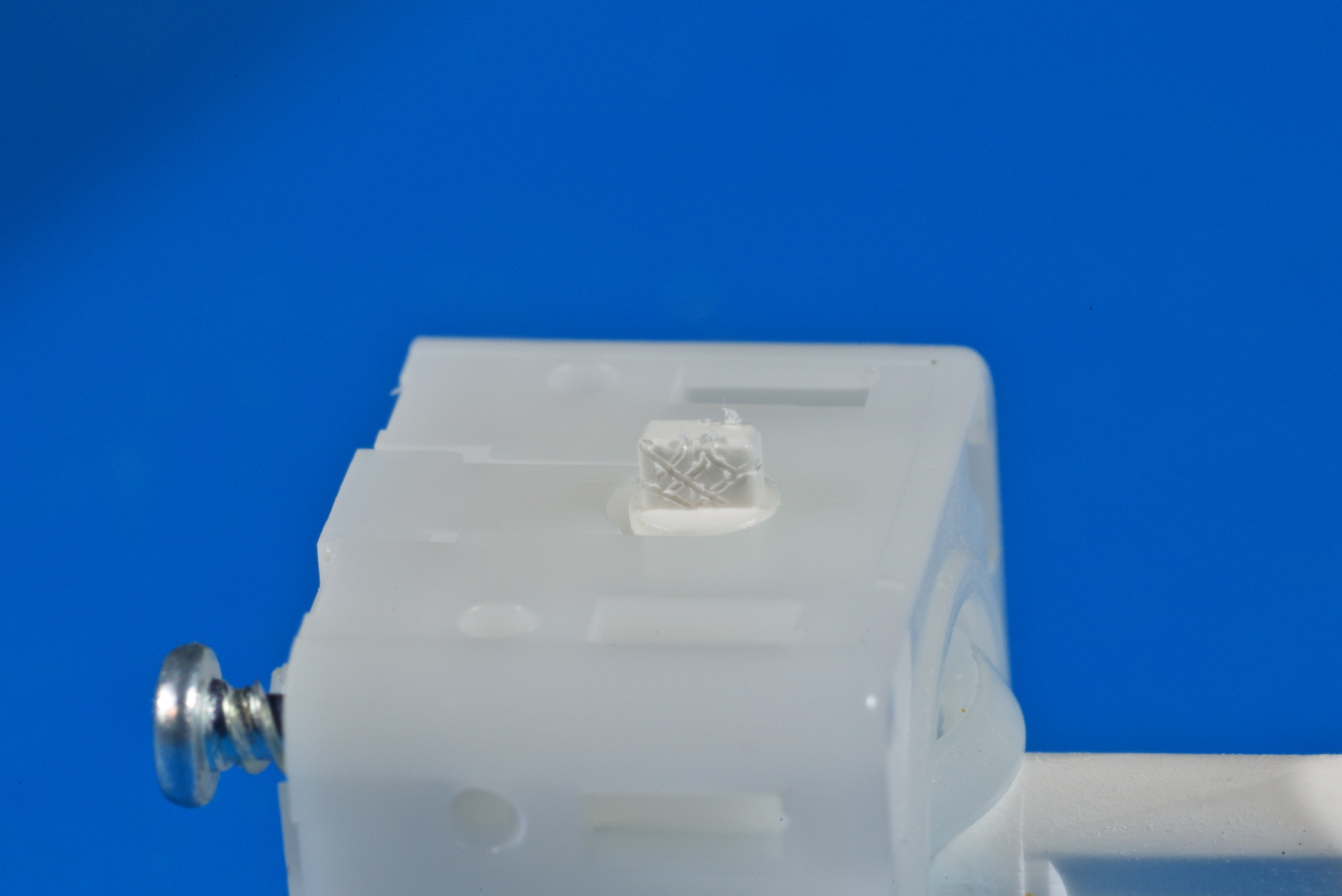
Do not apply superglue to the pegs!
Press-fit the magnet holders over the pegs, making sure that the hole for the magnets is offset downward.
The ideal offset may vary with different magnets, and different magnet/offset combinations may result in slightly different stick behavior.
Coat the inside of the magnet hole, and the top of the peg, with superglue. I prefer thin superglue.
Be very sparing with superglue so you do not contaminate the stickbox!
Make sure the magnet holders are able to rotate as you move the stick. If they are stuck, break them loose by grabbing the magnet mount, not by forcing the stick.
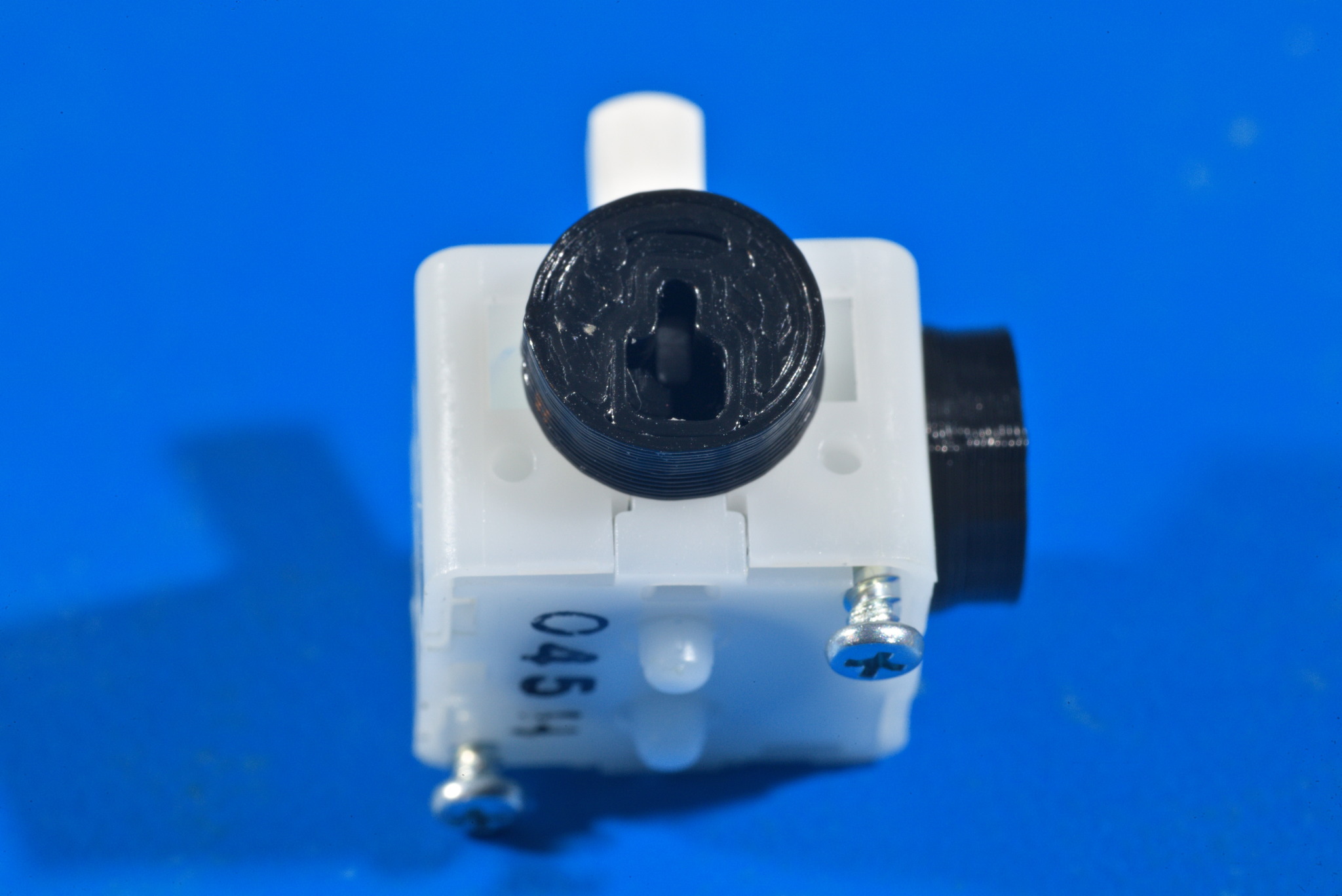
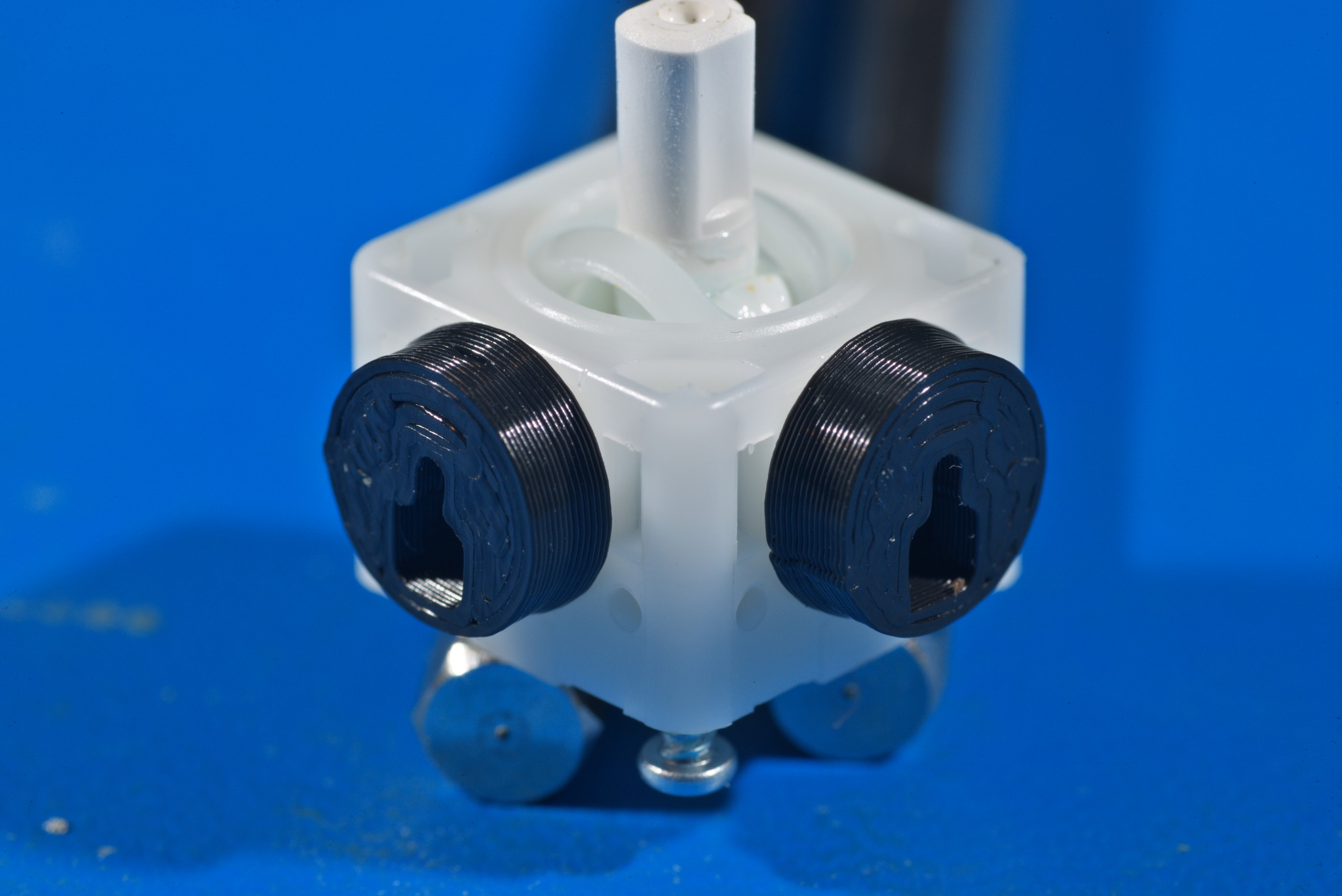
Insert magnets into the magnet wells, making sure that the magnets are all oriented horizontally.
If the magnets are not horizontal then the stick will not function.
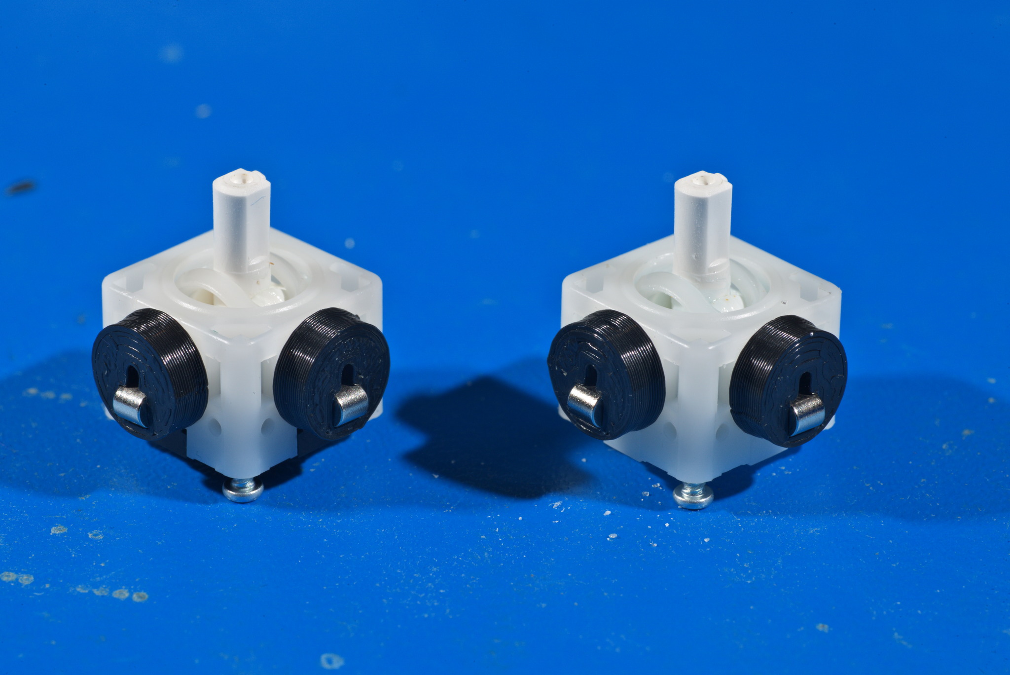
If you wish, you can add extra superglue on top of the magnets to ensure they are securely held in place, though this is not absolutely necessary.
Set the stickboxes aside to cure.
Stuck Trigger Prevention
This is an optional but simple and highly recommended step to improve the reliability of GCC triggers.
First, use a JIS #1 screwdriver to unscrew these four screws from the backshell of the donor GCC. If you attempt to use a Phillips screwdriver, you are extremely likely to damage the screw heads by camming out. Please use a JIS screwdriver so that any future modders working on the controller will have an easier time removing them.
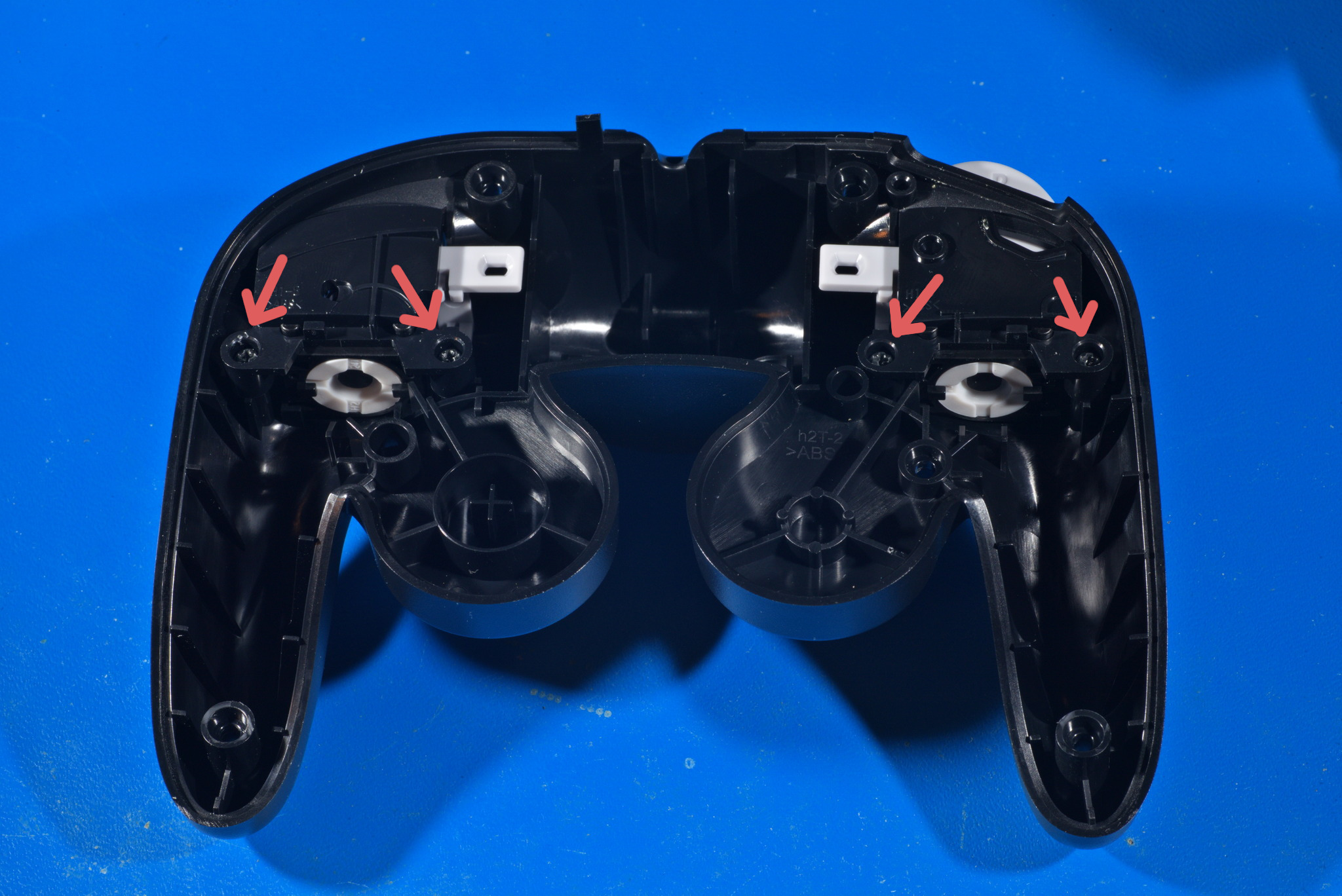
Remove the plate above each trigger and the trigger components, and find this protruding corner on each side.
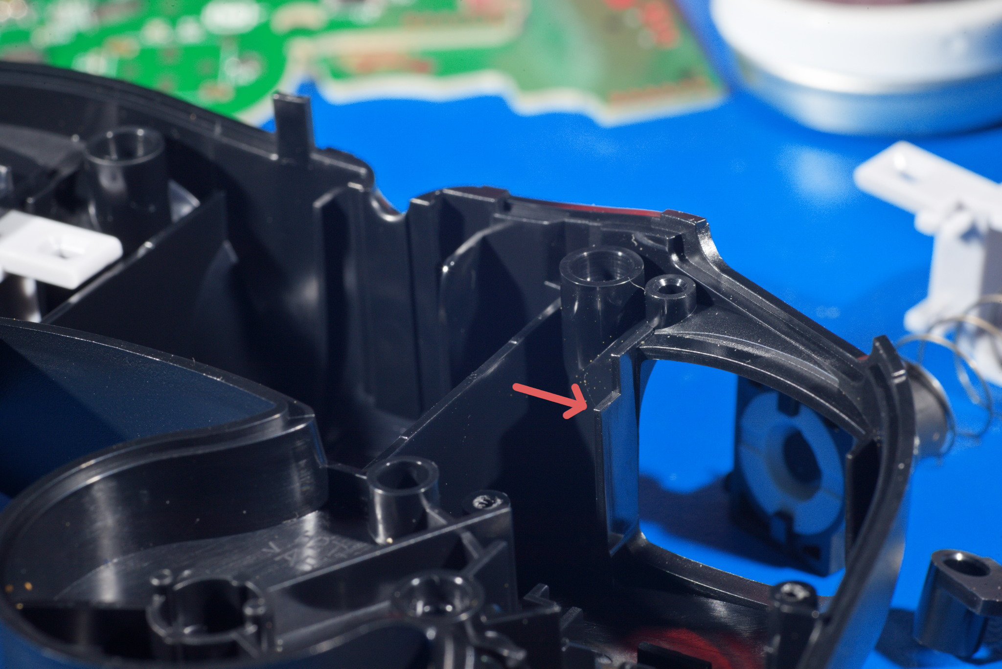
Using your flush cutters, remove about 1mm of height from the top of this corner.
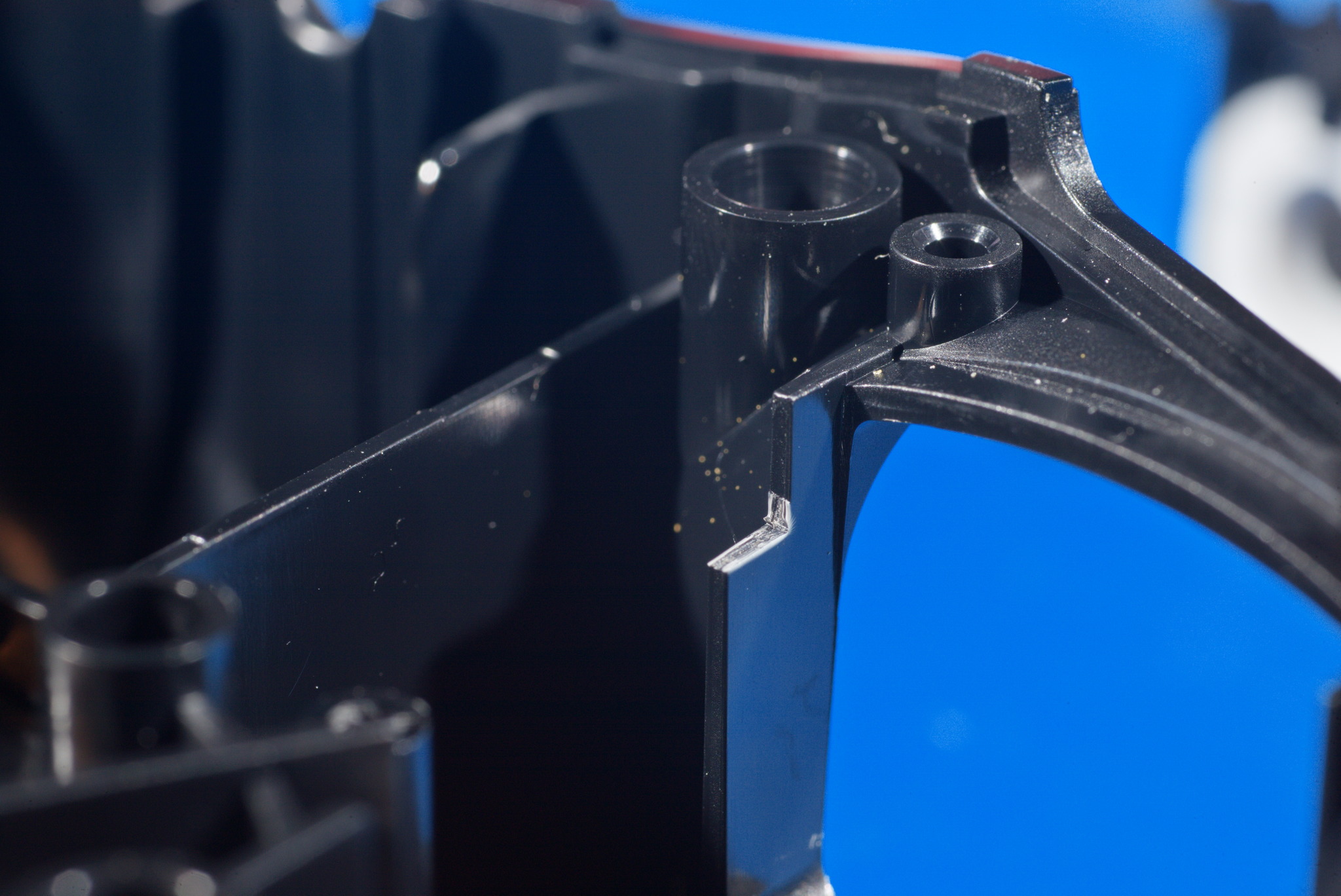
This ensures that the tab on the trigger that moves the trigger potentiometer does not get caught on that corner.
Soldering Interlude
Many people attempting to build PhobGCCs are new or relatively novice solderers. In this section I outline the basic processes and techniques involved in soldering in the hopes of making the process go more smoothly.
Soldering is basically applying fancy conductive hot glue to the surfaces, with some important differences. The first difference is that the parts that are getting soldered together must be very hot in order for the solder to stick. Additionally, the parts that are being soldered are usually damaged by too much heat, or heat applied for too long. Finally, the oxidation on the surface of the metal must be stripped off somehow.
These must all be considered together in order to successfully solder.
Heating
First, in order to properly heat the joint, you need to heat the joint to above the melting temperature of the solder. This involves a few considerations.
First is the melting temperature of the solder, which you use to determine the iron temperature.
- Leaded Sn63Pb37 solder melts at 183C/361F, and is usually soldered with the iron at 315-340C/600-650F.
- Lead-free SAC305 (Sn 96.5%, Ag 3%, Cu 0.5%) solder melts at a higher temperature of 217C/423F, and is usually soldered with the iron at 340-370C/650-700F.
If you set the iron too cold, it takes too long to heat the joint to a sufficient temperature, and nearby parts may be overheated and damaged. Conversely, if you set the iron too hot, the joint itself can be overheated and this can cause damage to the pads on the PCB or lift traces. I recommend you use the lower end of the temperature scales I listed as a starting point.
The second consideration is your soldering iron and its tips.
Make sure you are using a temperature-controlled soldering iron that can be set to specific temperatures, not just power levels. If it’s not temperature-controlled, just don’t use it. A non-controlled iron will heat up to hotter than you want when it’s not being actively used, and cool down to lower than you want when it’s being used. It’s not worth the suffering involved. You will hate the iron, hate yourself, and in all likelihood end up with nonfunctional PhobGCCs.
Do not use the following kind of soldering iron with the tiny dial on the handle. I call these “Phob Destroyers” because they do not have actual temperature control. They are cheap, and you get what you pay for: garbage.
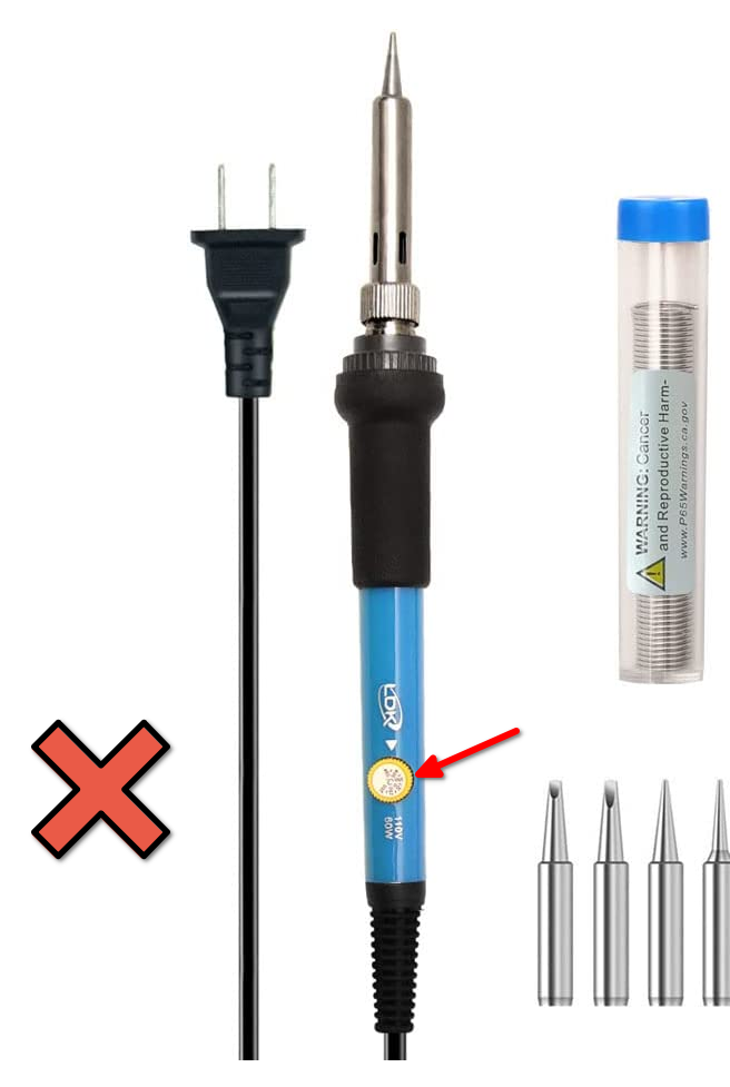
Next is the tip size. In general, you want to get the most contact between the tip and the solder joint without touching adjacent joints. Ideally, you use a chisel tip that is exactly as wide as the pads. Most people don’t switch soldering iron tips frequently, so in this case you should select the widest tip usable for the smallest joints. PhobGCC 2 is much easier to solder than PhobGCC 1, so I recommend either chisel tips at least 1.6mm wide or knife tips that are significantly wider.
Additionally you have to consider tip condition when heating. When metal is left at a high temperature, the metal surface reacts with oxygen in the air to form an oxide layer that insulates the tip, preventing heat transfer, and also doesn’t let solder stick to it. It is important to keep the tip tinned with fresh solder or tip-tinner whenever it is not in use. While the solder oxidizes, it is also liquid at operating temperature so any oxidation of it can be easily wiped off with a wet sponge before beginning to solder. If the tip has oxidized significantly, you can scrub off the oxide coating using a brass wool sponge, followed immediately by dipping the tip in tip tinner or alternatively coating the tip with normal solder. If you aren’t using your iron for a while, make sure to turn it off to stop it from oxidizing.
Finally, it comes down to technique. In order to transfer the heat as effectively as possible, apply a lot of pressure using the soldering iron to both parts that you want to join together. The board is robust, so you can press down on it very hard, and press across onto pins as hard as you can without bending them, which may vary based on the pin thickness.
Removing Oxidation from Surfaces
While oxidation quickly grows thick on very hot metal like the soldering iron tip, a thin layer exists on almost every metal. To remove this, a material called flux is applied. When flux is heated, it becomes reactive and strips the oxygen out of the metal oxides. This lets the solder bond properly to the surface.
Most solder has a flux-core, where flux is actually inside the solder wire so that it is automatically applied when you melt the solder. Do not get solder that is “solid wire”. There are various kinds of flux as well. You should get no-clean rosin flux. More active flux types are useful when soldering to different materials, but you don’t need any more than no-clean rosin flux for the gold-plated board of the PhobGCC. If you do use more active types of flux, then you need to clean the board off after soldering in order to prevent corrosion.
In addition to flux core, if you are having trouble, you can add additional flux, which can come as a gel, a liquid in a syringe or bottle, or in a pen. I personally only use added flux for tinning the ends of stranded wire.
To effectively use flux-core solder, you must apply solder to the joint, not to the iron. If you apply solder to the iron, all the flux gets used up on the surface of the iron and there’s no effect on the joint surfaces that you want to bond to. Additionally, if you apply solder to the joint and not to the iron, you can be sure the joint is hot enough before the solder is applied. Another benefit is that this lets you better control the amount of solder. If you touch the solder onto the iron tip, you might end up with a big blob of solder on the iron tip and none on the board.
General description of technique
First, turn on the iron and wait for it to heat up.
Then, for each joint:
- Scrub off oxidation on soldering iron tip with brass wool.
- Tin the tip with solder or tip tinner.
- Clean most of the tinning off the tip with brass wool or wet sponge.
- Strongly press the tip against both parts that are being soldered together.
- Apply flux-core solder wire to the joint between the two parts without touching it to the soldering iron tip.
- Wait for the solder to melt, then feed the wire in until it forms a concave cone. Do not apply too much.
- Continue heating a second or two more to let the flux in the joint stop bubbling.
- Remove the soldering iron and let the joint cool without blowing on it.
- Continue with other adjacent joints.
- When you’re done soldering for now, clean the tip with brass wool or sponge.
- Apply fresh solder or tip tinner.
Cleaning Flux
If you leave flux behind from soldering, it can cause problems. One thing is that the flux residue itself can be conductive, which can cause the Hall sensors to not work properly. This is especially problematic with flux that isn’t labeled as No-Clean. Additionally, the flux residue is corrosive and can cause the components to corrode long-term.
To remedy this, use rubbing alcohol (as high concentration as you can get) with a cotton swab to clean the flux residue from the PCB when you’re done soldering.
One thing of note is that no-clean flux is notably difficult to clean. When activated, it turns into a gummy, sticky substance. If you do intend to fully clean every part you make, flux that is not no-clean is actually easier to clean off of the solder joints. Non-no-clean flux forms a much harder, brittle substance that flakes off relatively easily.
Board Preparation
The C-Stick daughterboard comes attached to the main PhobGCC motherboard. You will have to remove it.
To do this, first simply snap it off at the motherboard side. You can use your bare hands, but be careful to avoid touching the button contacts, such as for the Start button, or you may contaminate them with oil.
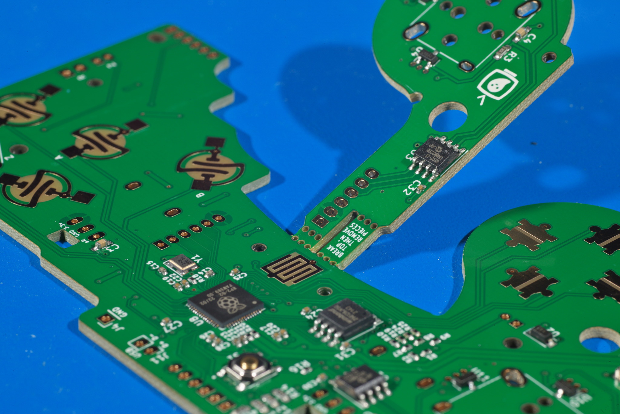
Then, break the two “mousebites” off of the C-Stick daughterboard using pliers. Note that one is longer than the other; this is normal.
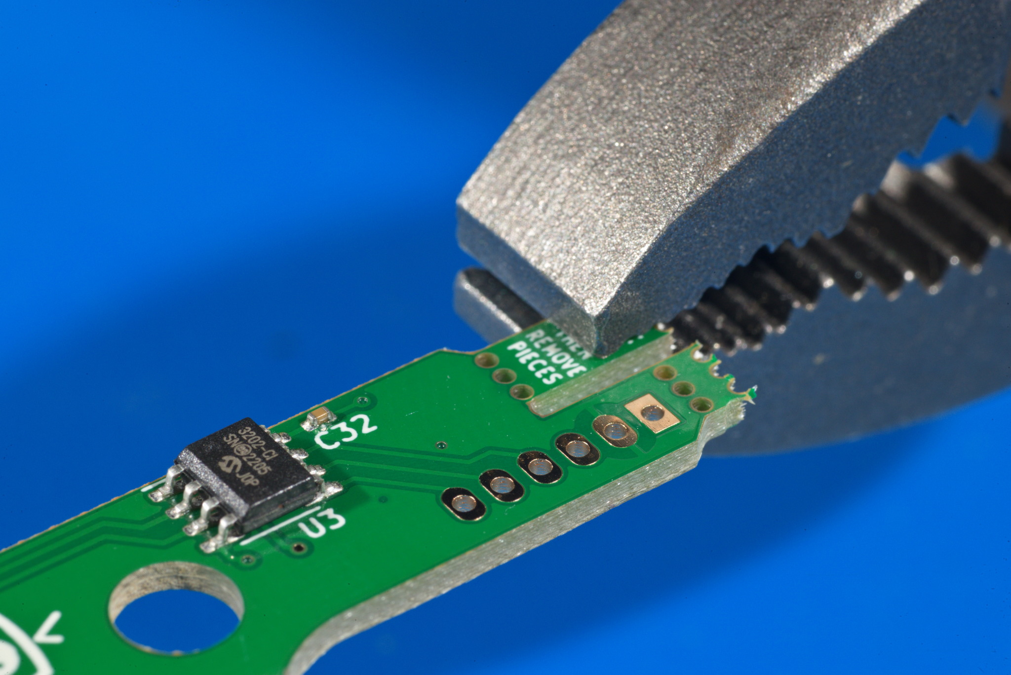
This should be the result.
RP2040 Programming
Next, load firmware onto the RP2040.
DO NOT WAIT UNTIL AFTER BUILDING TO FLASH FIRMWARE!!! Put firmware on first or else you won’t know if your board is dead, your USB cable is bad, or if you screwed something up when assembling.
You can download it here.
Plug the board into a computer via the micro USB port while holding button S1 on the motherboard, then release the button. It will appear as a USB mass storage device, which you need to open in a file browser. Drag-and-drop the .uf2 firmware file from the software release page into that drive. The mass storage device will disappear and you are done loading firmware on.
If you ever need to change or update the firmware, simply repeat the process.
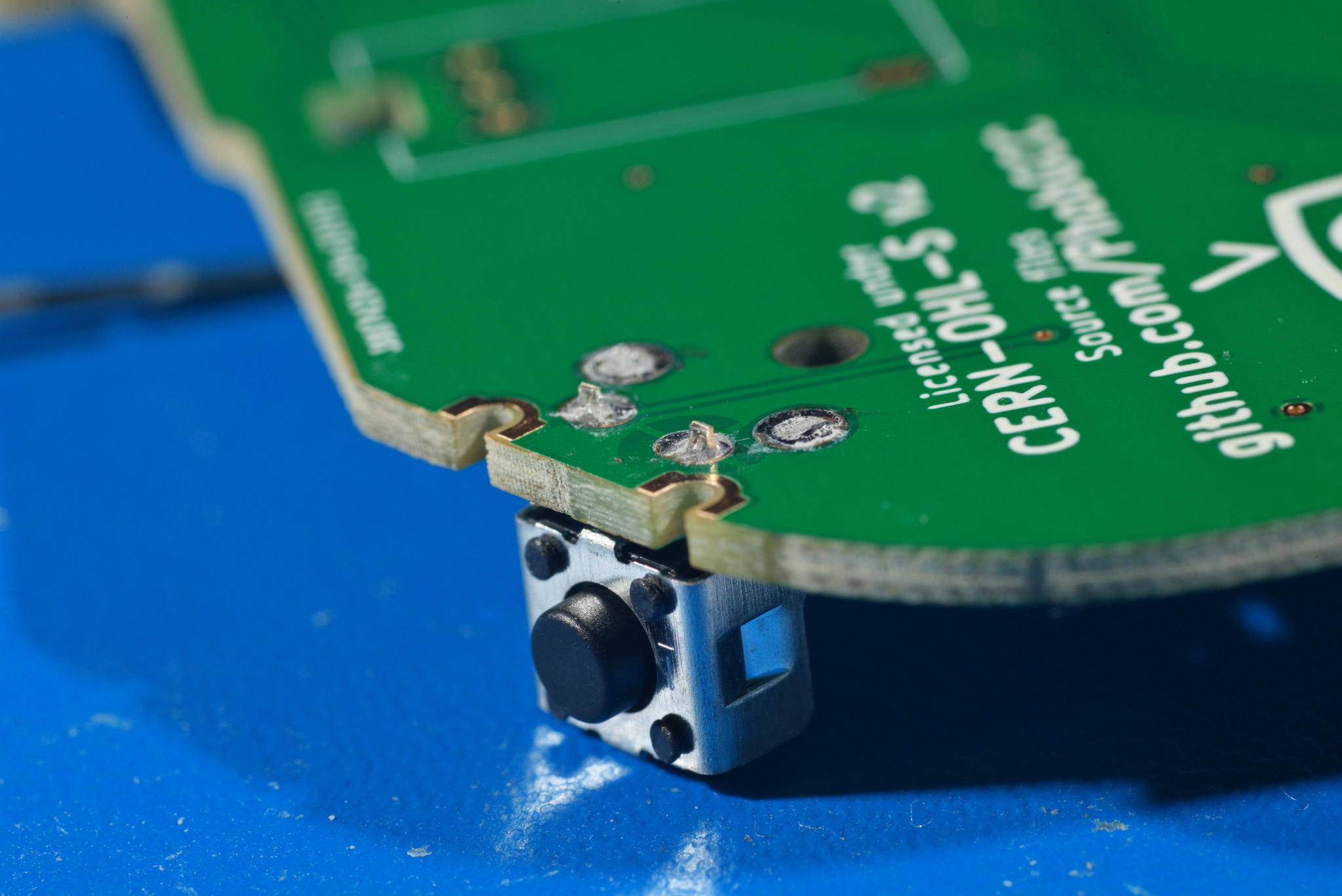
Z button Switch Soldering
The first soldering step is to solder the Z button switch on.
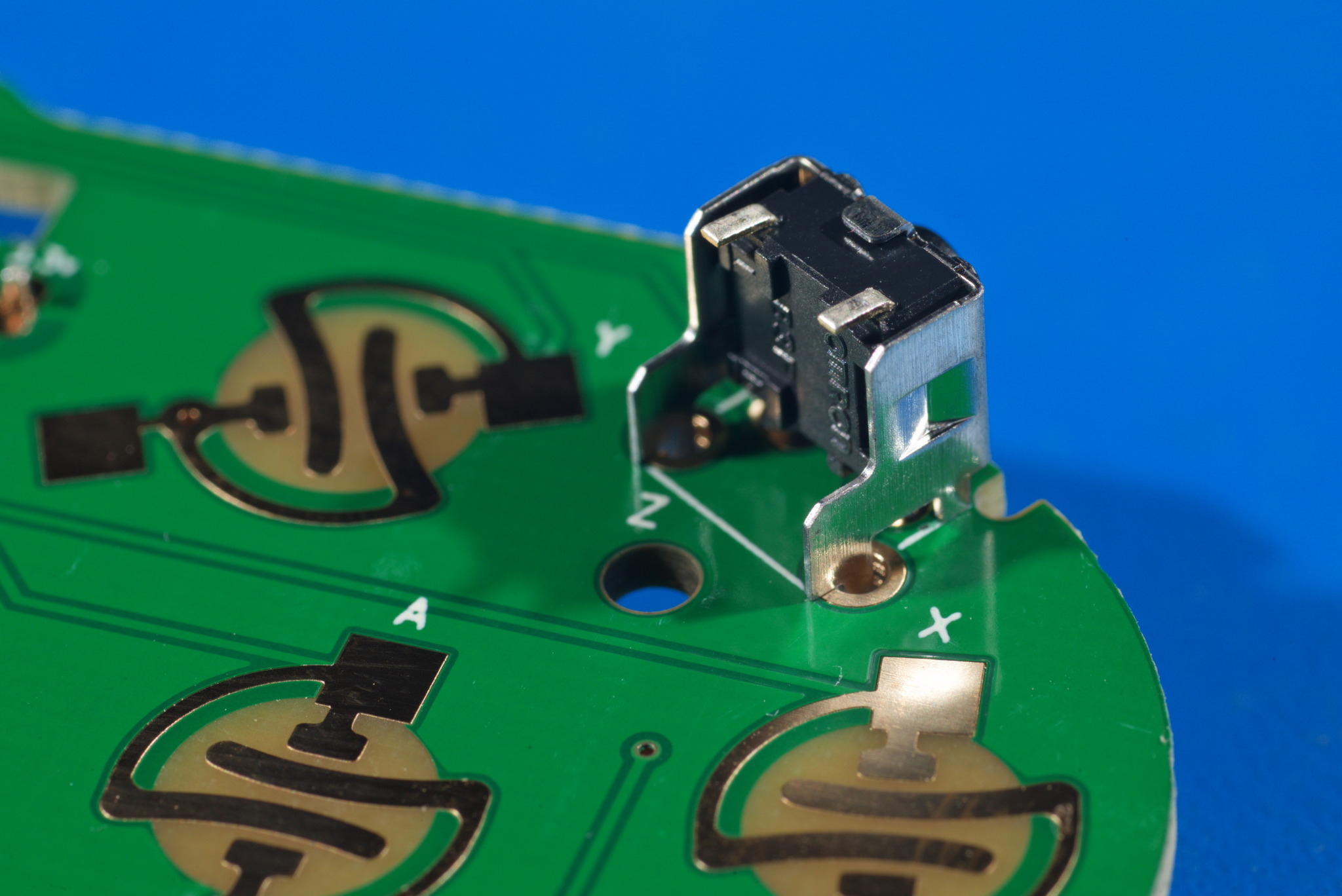
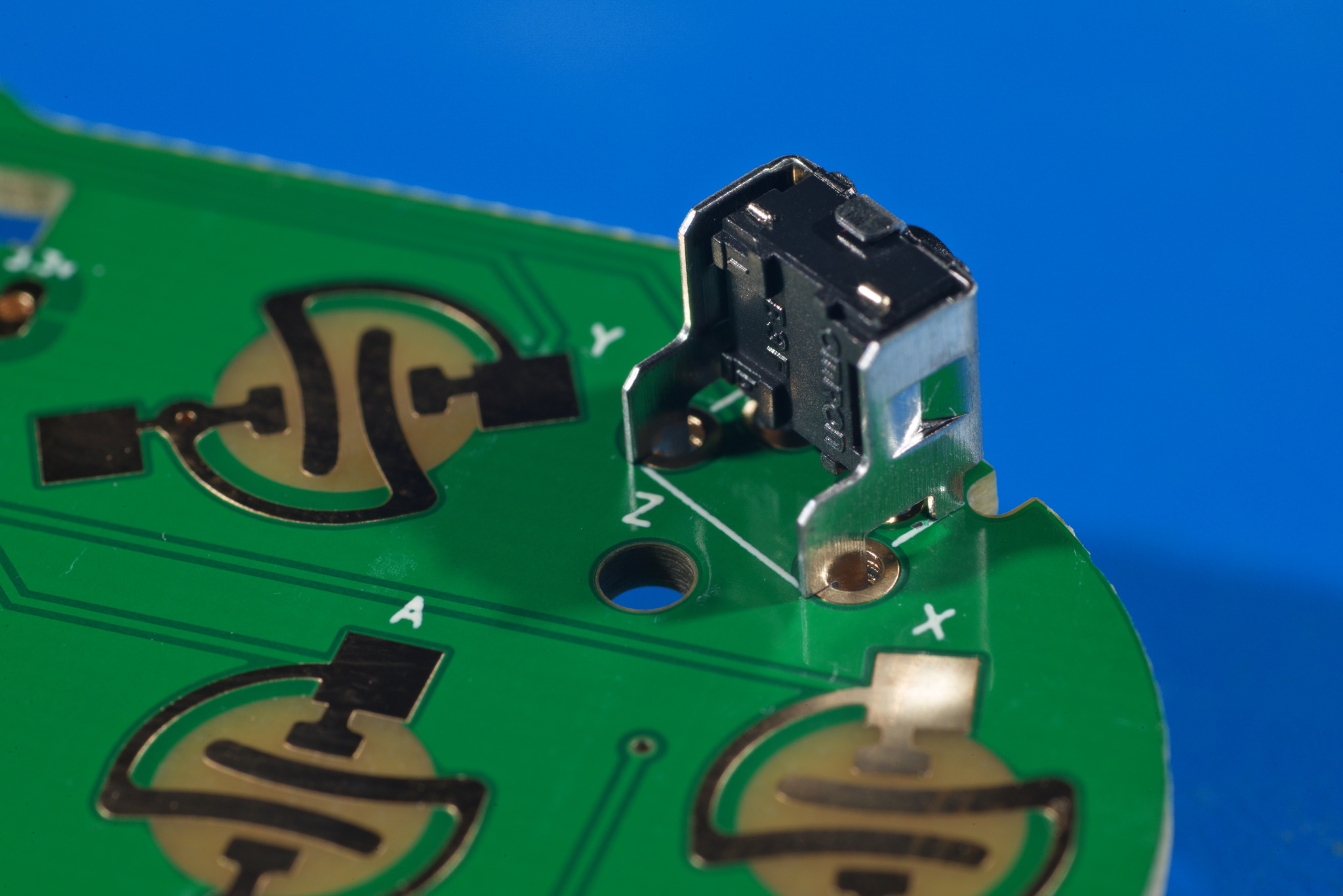
Make sure to put the button on the top side of the board where the silkscreen outline of the component is, not on the back.
Also make sure that the switch stands perfectly square to the board, or the board may not fit in the controller shell properly.
If you are using a Z button switch harvested from an original GCC, you can ignore the two large circular holes.
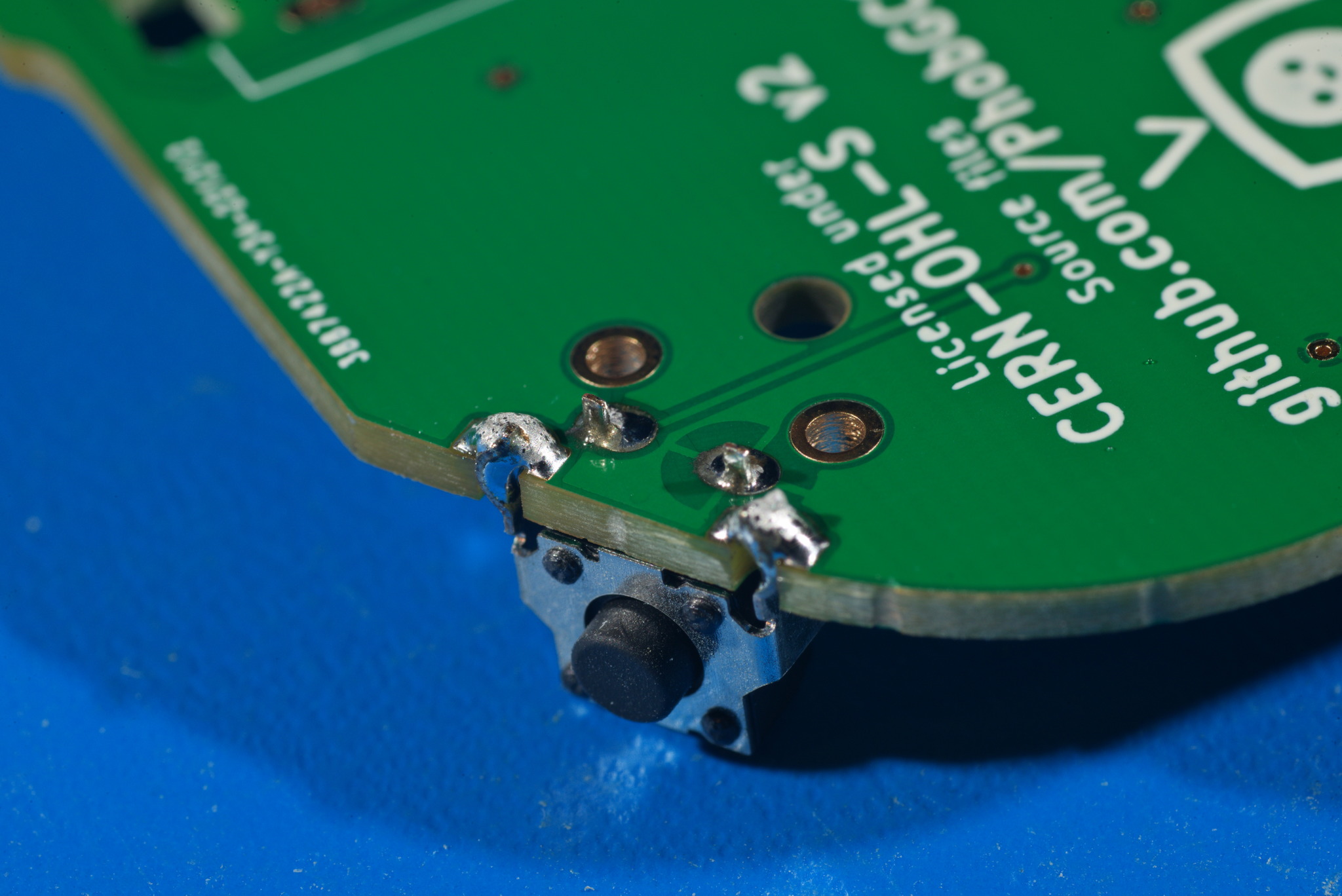
If you are using an Omron tactile Z switch as listed in the parts ordering guide, here are the slight tweaks you must make.
Firstly, trim the two leads off the top of the button. These interfere with a rib on the front shell.
Secondly, when you solder, don’t use the U-shaped solder pads at the board edge. Instead, the structural legs go through the larger holes farther from the board edge.
Make sure to not overfill the holes for the structural legs; you want the solder to sit entirely below the surface.
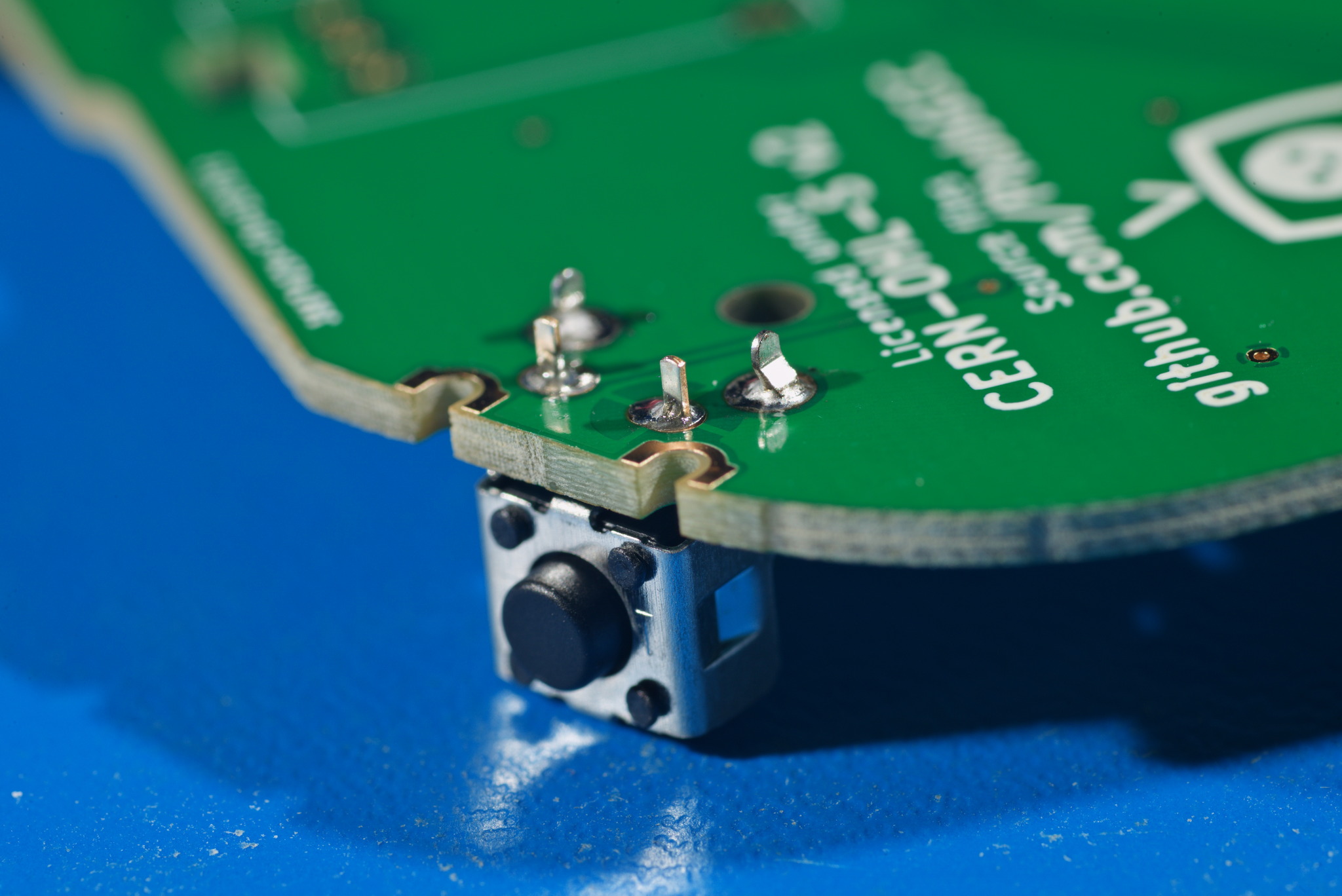
This is because you will need to trim the structural legs completely flush in order to not interfere with the trigger guards.
Additionally, you need to make room for the structural legs on top by trimming the button rubber as follows:
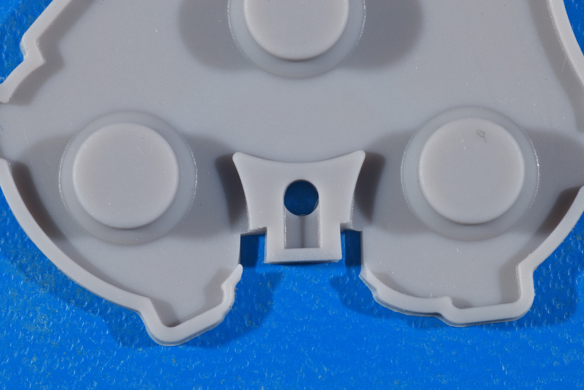
As a note for later, it may take a little more force than you may be used to when inserting the motherboard into the front shell when you use an Omron tactile Z switch.
This is normal, and does not cause any issues.
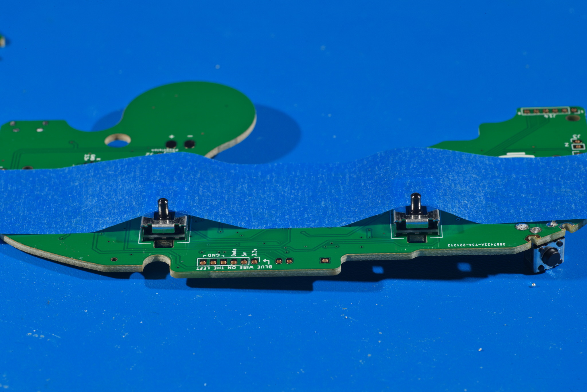
Trigger Potentiometer Soldering
Mount the trigger potentiometers to the back of the board. Do not mount them to the front side with all of the chips.
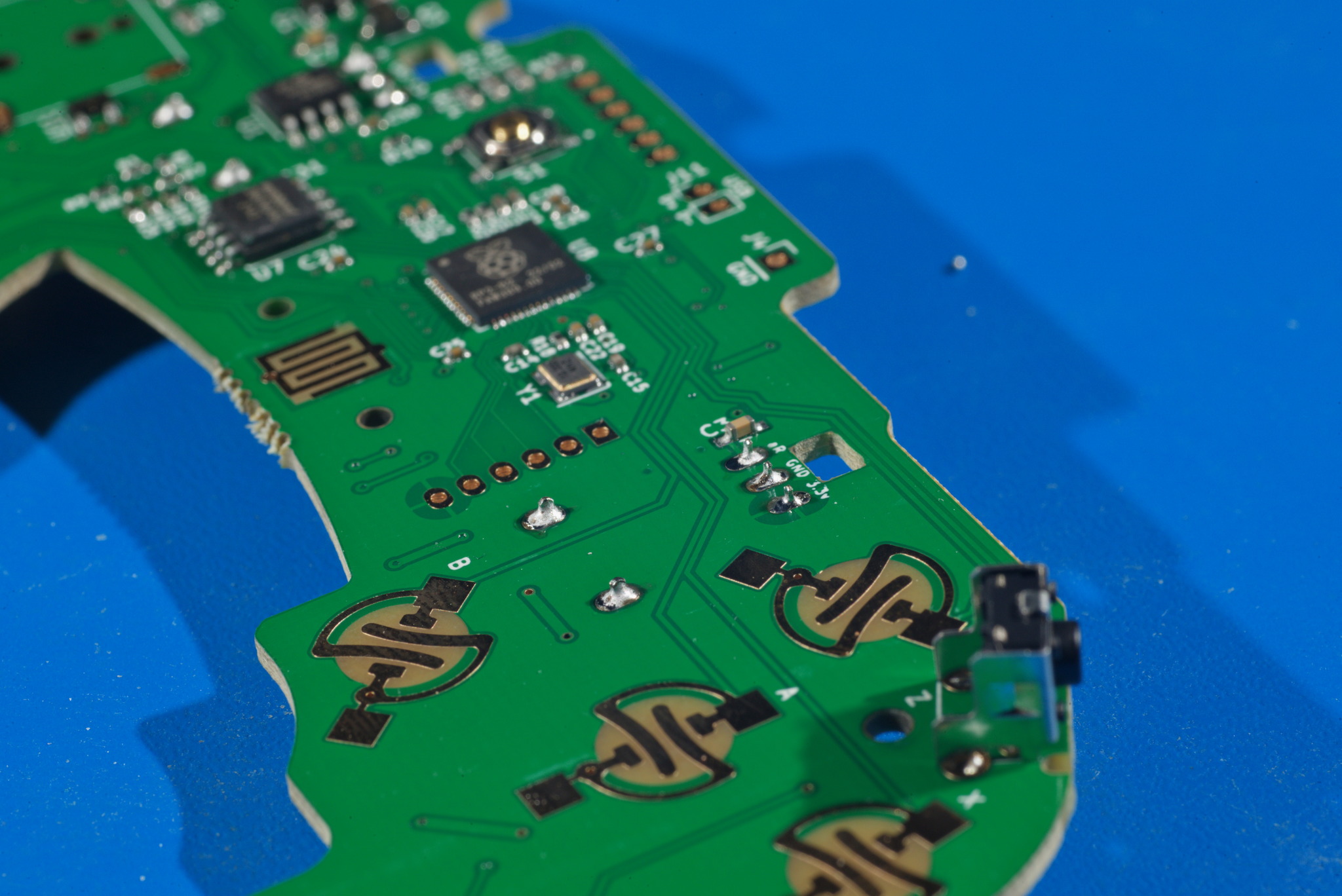
To secure them when soldering, you can tape them to the board with masking tape, or just rest the board on top of the potentiometers.
Be sure to check after soldering your first joint that the potentiometer is laying flat against the back of the board before continuing.
C-stick Cable Soldering
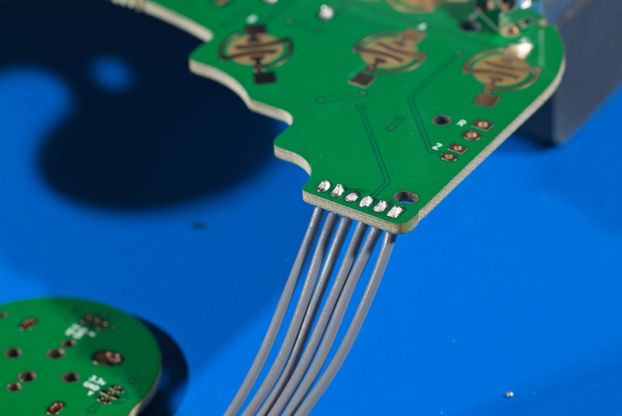
For PhobGCC 2, the C-Stick now needs six conductors connecting it to the main motherboard.
You will have to provide your own wire for this, though there may come to be brand-new ribbon cables available that may suit the purposes. Any such ribbon cables should be between 1 and 1.5 inches long (25 to 38mm) and must be 2 millimeter wire spacing. We strongly discourage the use of ribbon cables harvested from other controllers, as poorly folding previously-used ribbon cables has been a major cause of issues with PhobGCCs in the past.
In this guide I cut and stripped six 1.5-inch (38mm) wires identical to those used in the trigger paddles, and applied flux to the ends.
Then, I used the same technique as in the Trigger Paddle Soldering section to install them in the back side of the C-Stick daughterboard.
Note that this is the side with silkscreen around the through-holes.
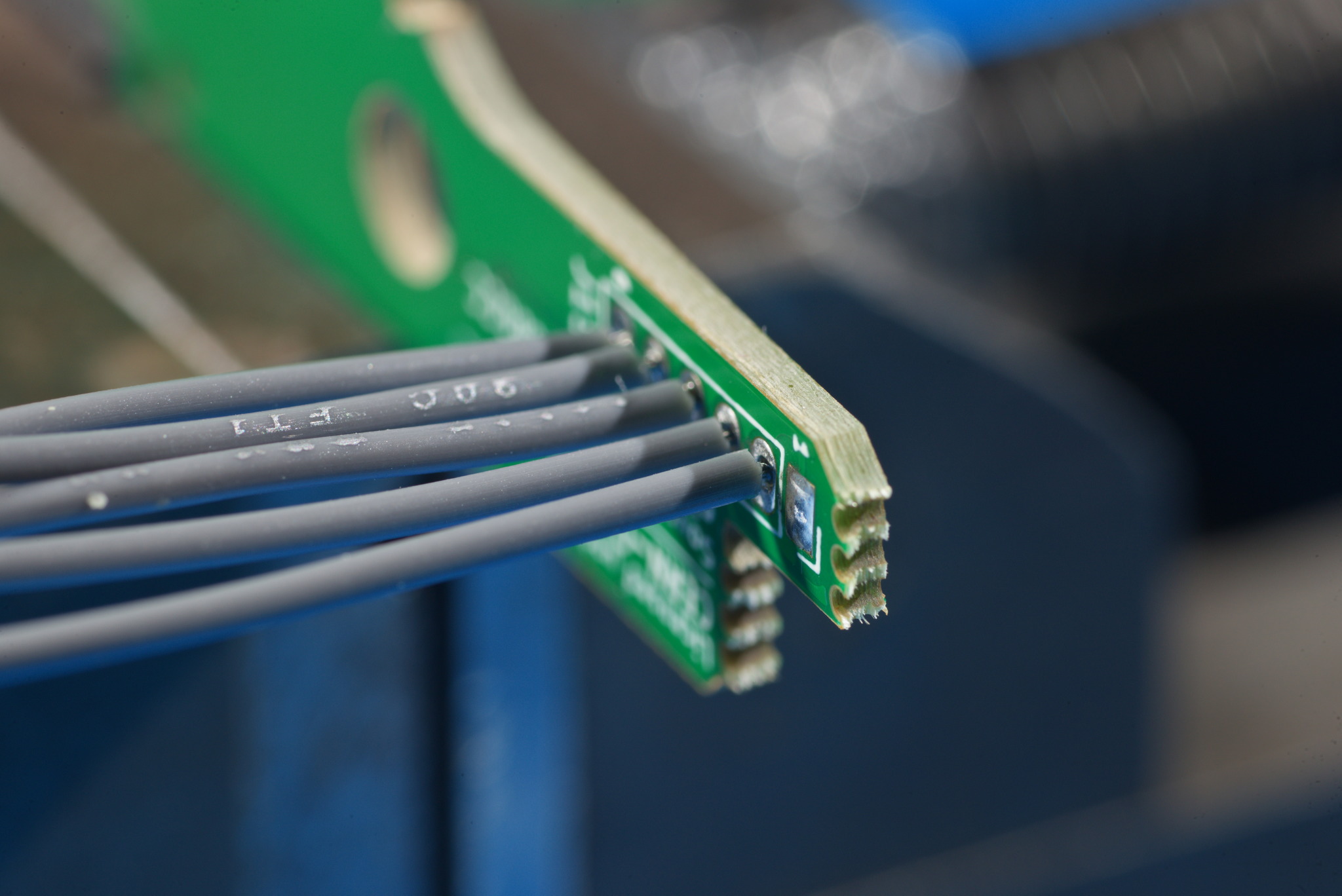
For these especially, if you are using individual wires I strongly recommend that you make their lengths as consistent as possible, and solder them such that the insulation ends at the same distance from the C-stick daughterboard.
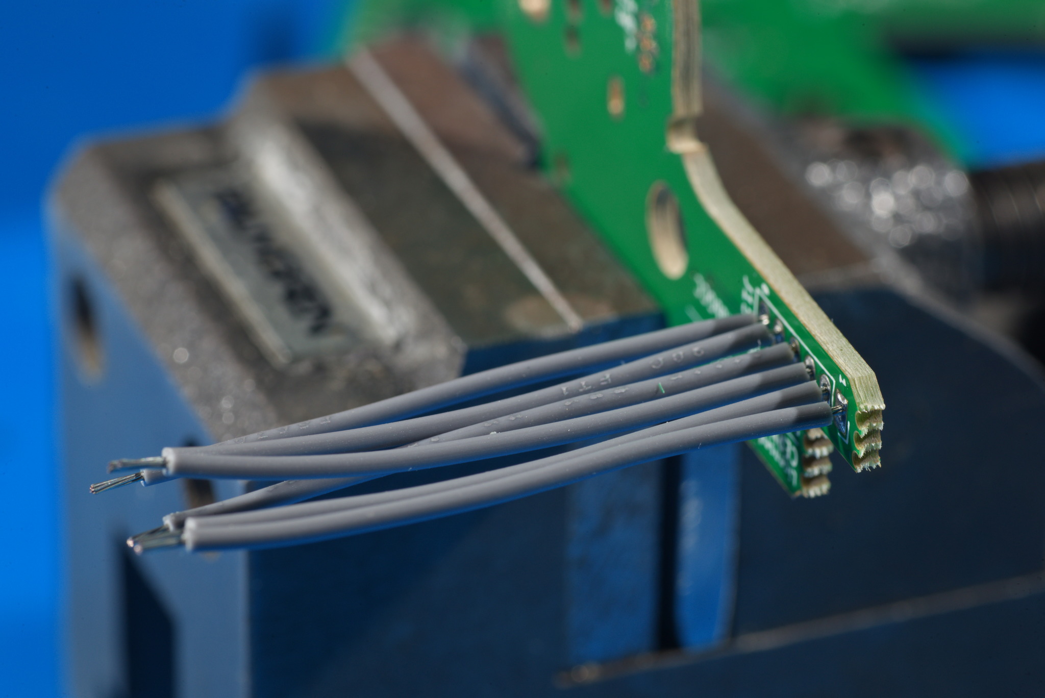
The uniform length helps when you are inserting the wires into the motherboard.
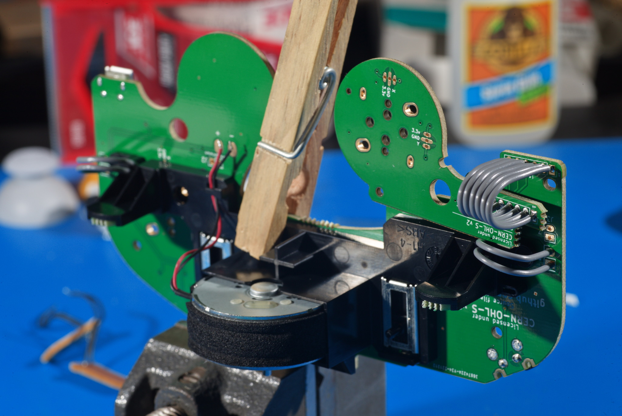
Support the motherboard above the C-Stick daughterboard with the daughterboard oriented like this.
If you flip it around, the C-stick will not function at all.
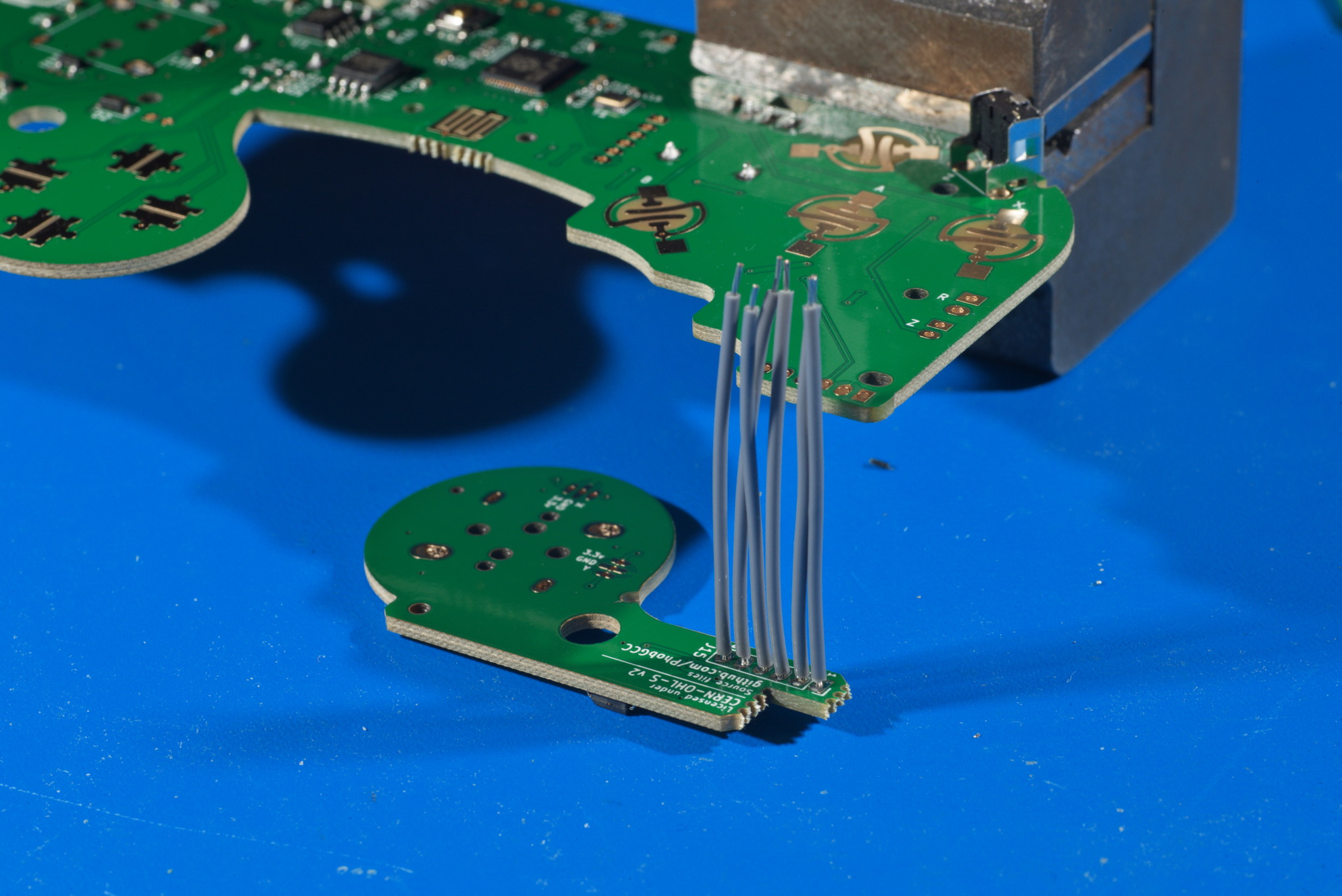
Insert all of the C-Stick wires into the motherboard.
Make sure that all of the wires are straight and none of them are crossed, or the C-Stick will not function.
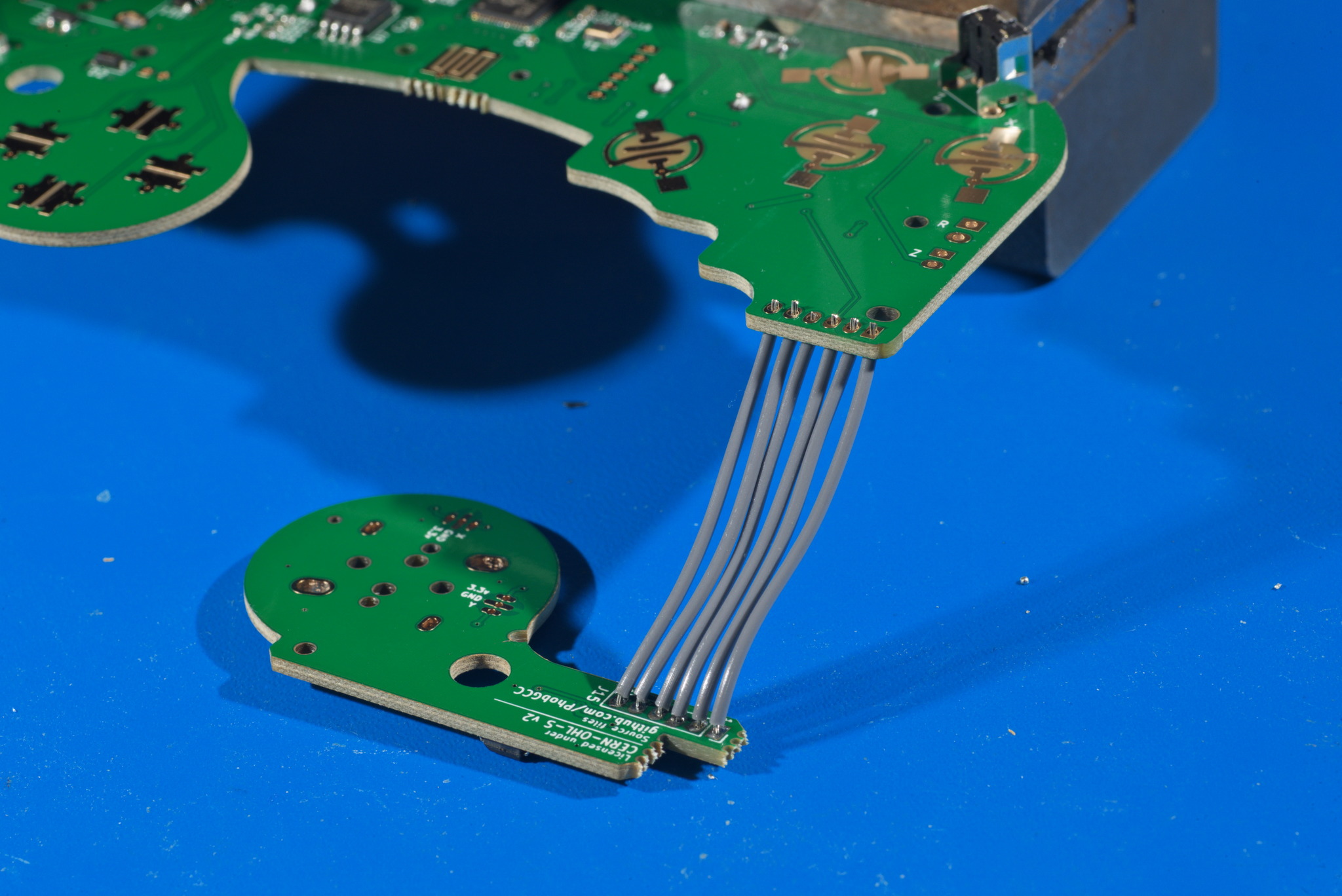
Then solder the wires.
Trigger Paddle Soldering
If you are using OEM trigger paddles, you may skip this step.
If you are using PhobGCC trigger paddles instead of OEM, you will need to solder wires to them yourself.
Cut four pieces of wire to about 1.5 inches (38mm) long and strip the insulation off the ends.
Apply flux to the ends of the wires, making sure not to cause them to fray if using stranded wire.
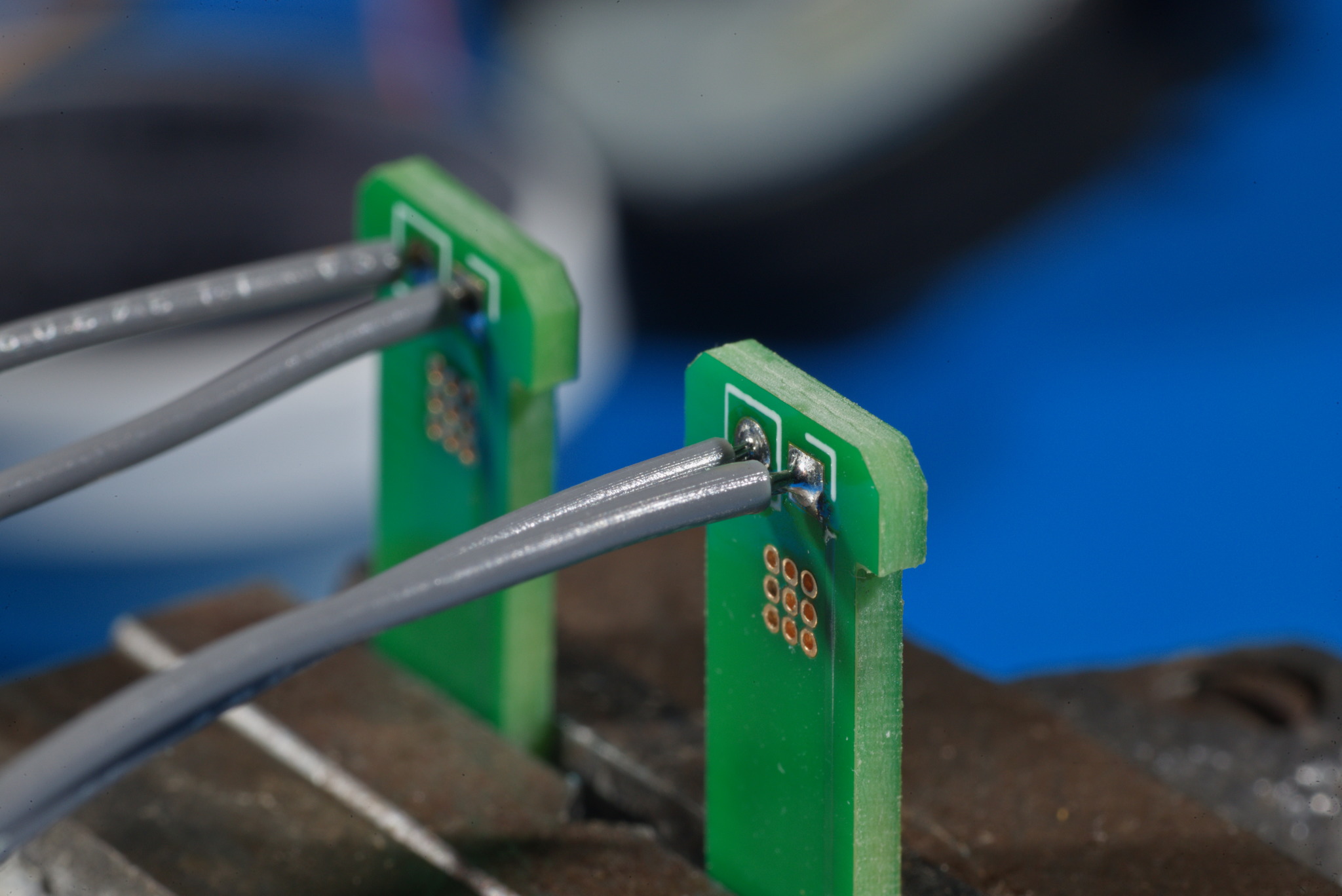
Hold the trigger paddles in a vise and apply solder to fill the through-hole pads with solder.
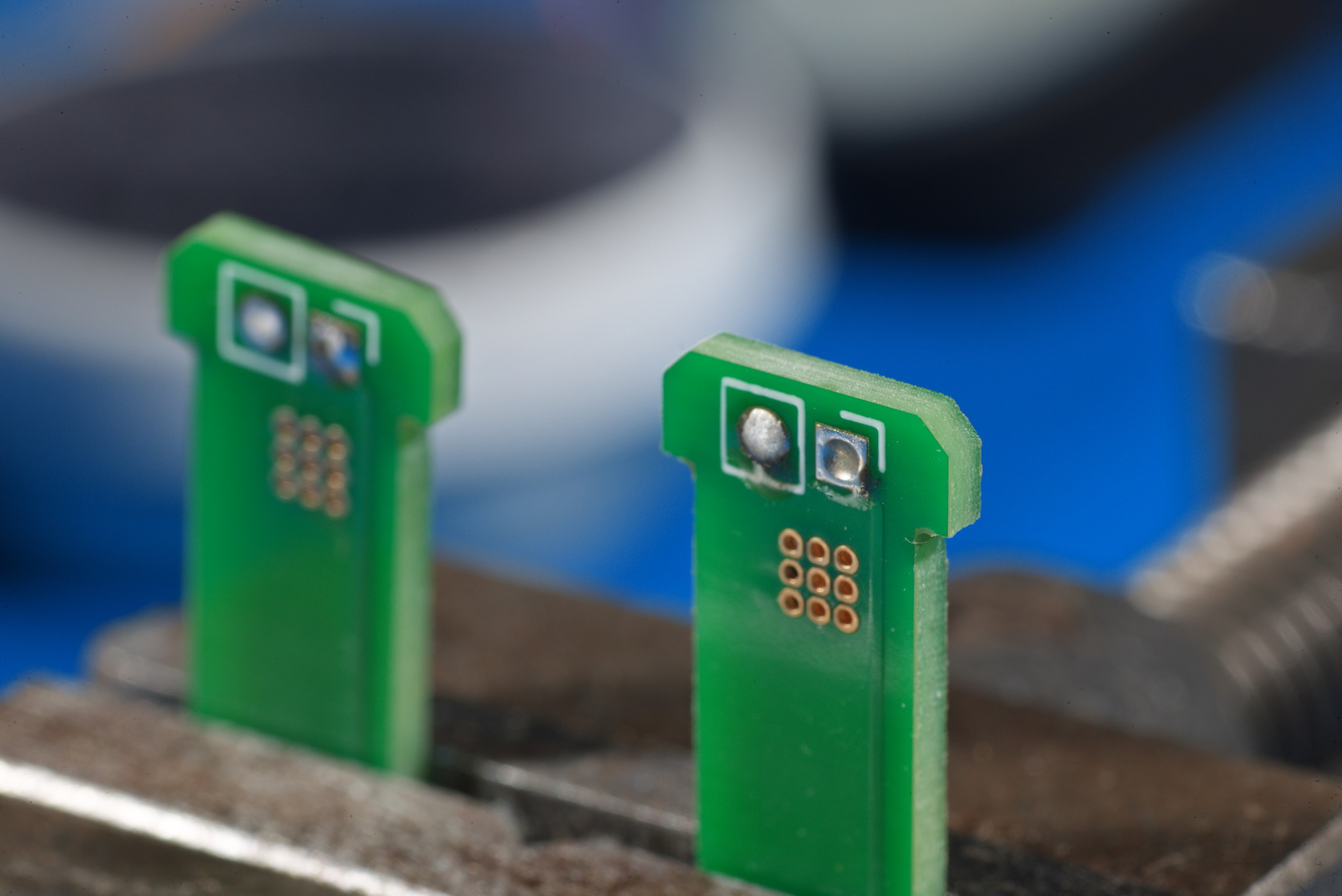
Then, heat the front side of each through-hole with your soldering iron to melt it, and insert the fluxed end of the wire from the back side of the hole where the silkscreen markings are.
Stickbox Installation
Install the stickboxes on the motherboard and the C-Stick.
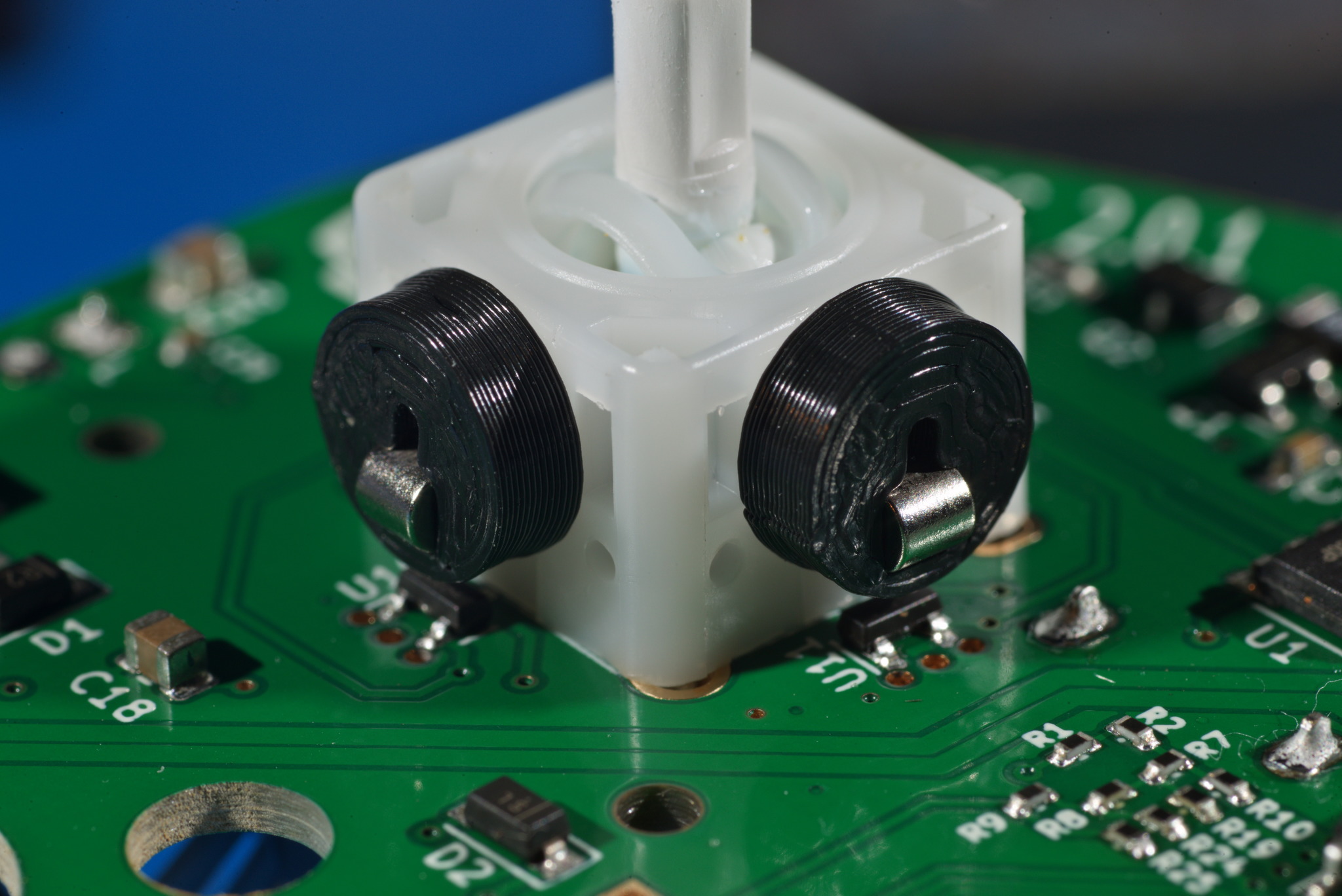
You must have the magnets mounted above the 3-legged SMD Hall-Effect sensors.
Note that on PhobGCC 1.2.3 and prior, the stickbox on the motherboard was 180 degrees off of normal, but on PhobGCC 2 the magnets must be on the bottom and right.
Trigger Paddle Soldering
Insert the trigger paddles into the rumble bracket (whether OEM or third-party), ensuring that the contacts on the trigger paddle are visible. Route the wires out the slots on the back of the rumble bracket.
Then mount the rumble bracket to the motherboard. Here I have put the rumble motor in the rumble bracket but that can be left until later. I like to hold the rumble bracket in place with a clothespin.
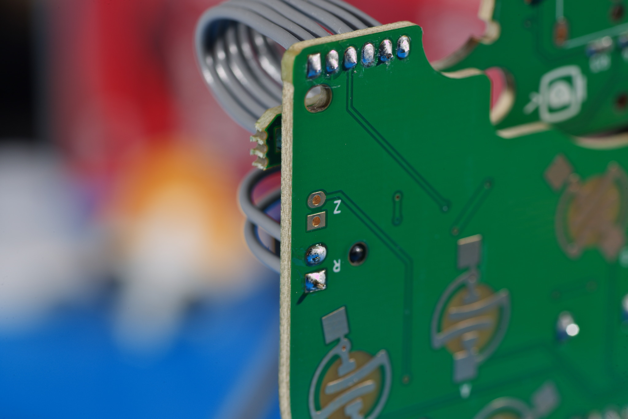
Tuck the wires from the trigger paddles into their respective holes on the motherboard.
For R, make sure not to mix up the holes with the extra holes for mouseswitch Z, which are nearby.
Then solder the wires in place.
Controller Cable Soldering
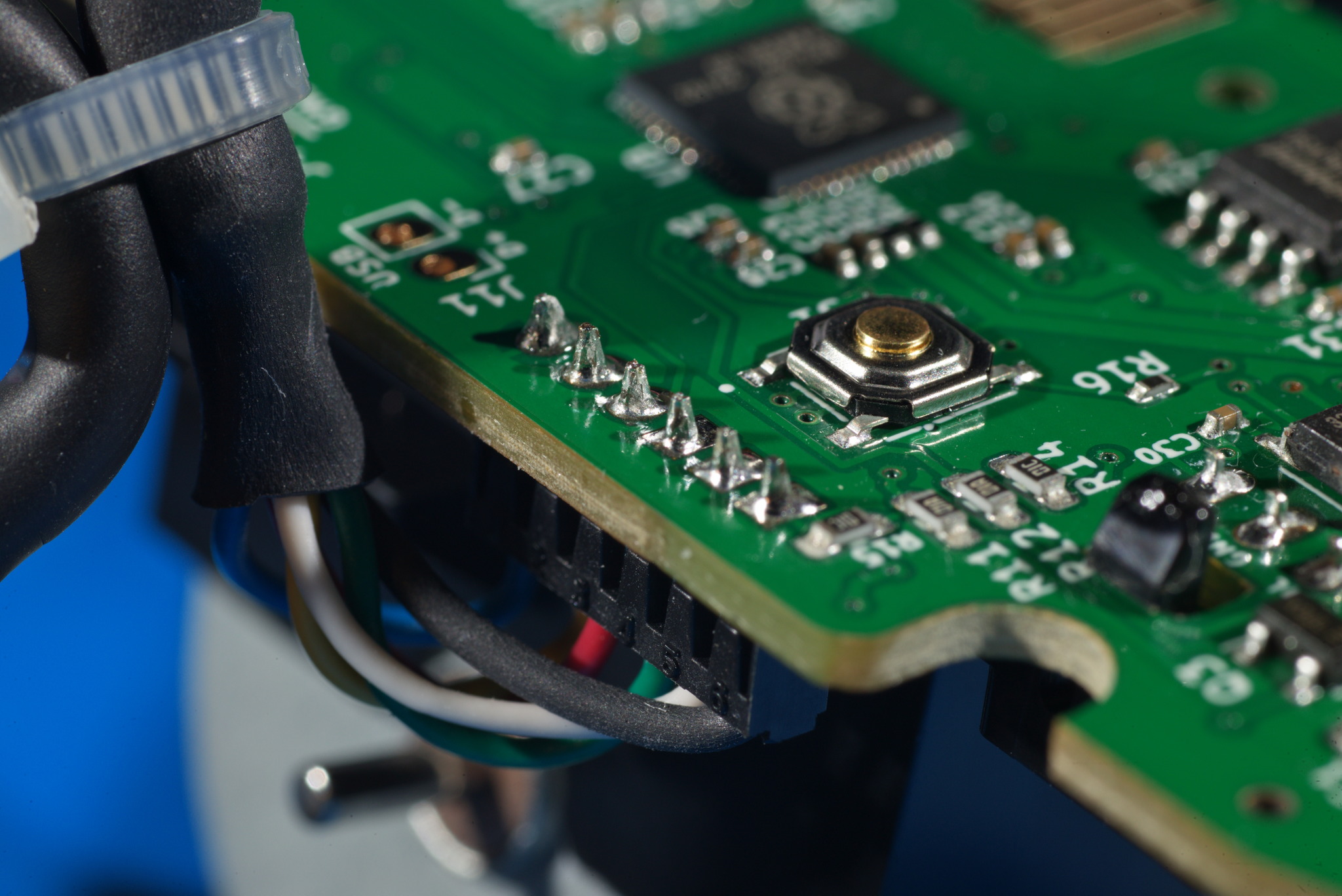
Next, install the controller cable into the motherboard.
The cable must go in the back of the motherboard.
If you are using an OEM cable harvested from a first-party Gamecube controller, the black wire should be placed farthest from the center of the controller, and the blue wire closest to the center of the controller.
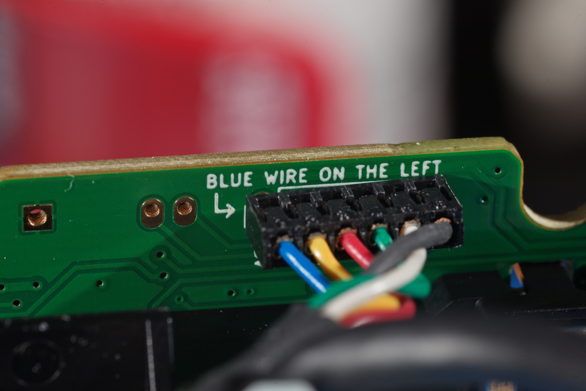
Secure the wire in place, then solder the pins to the pads on the top of the motherboard.
OPTIONAL PhobVision installation and soldering
PhobVision is a new feature exclusive to PhobGCC 2 where the controller can output composite video to a CRT and provide an actual user interface for the user to calibrate and configure the controller without having to blindly input memorized button combinations.
Here is a video demonstrating its basic functionality.
If you choose to install it, here’s my suggested method.
It’s rather irritating to pack this in with an OEM rumble motor, so you may want to do it with no rumble installed or with a cell rumble motor. Nonetheless, this guide shows you how to do it so that it fits around the OEM rumble.
Video Guide for backshell drilling
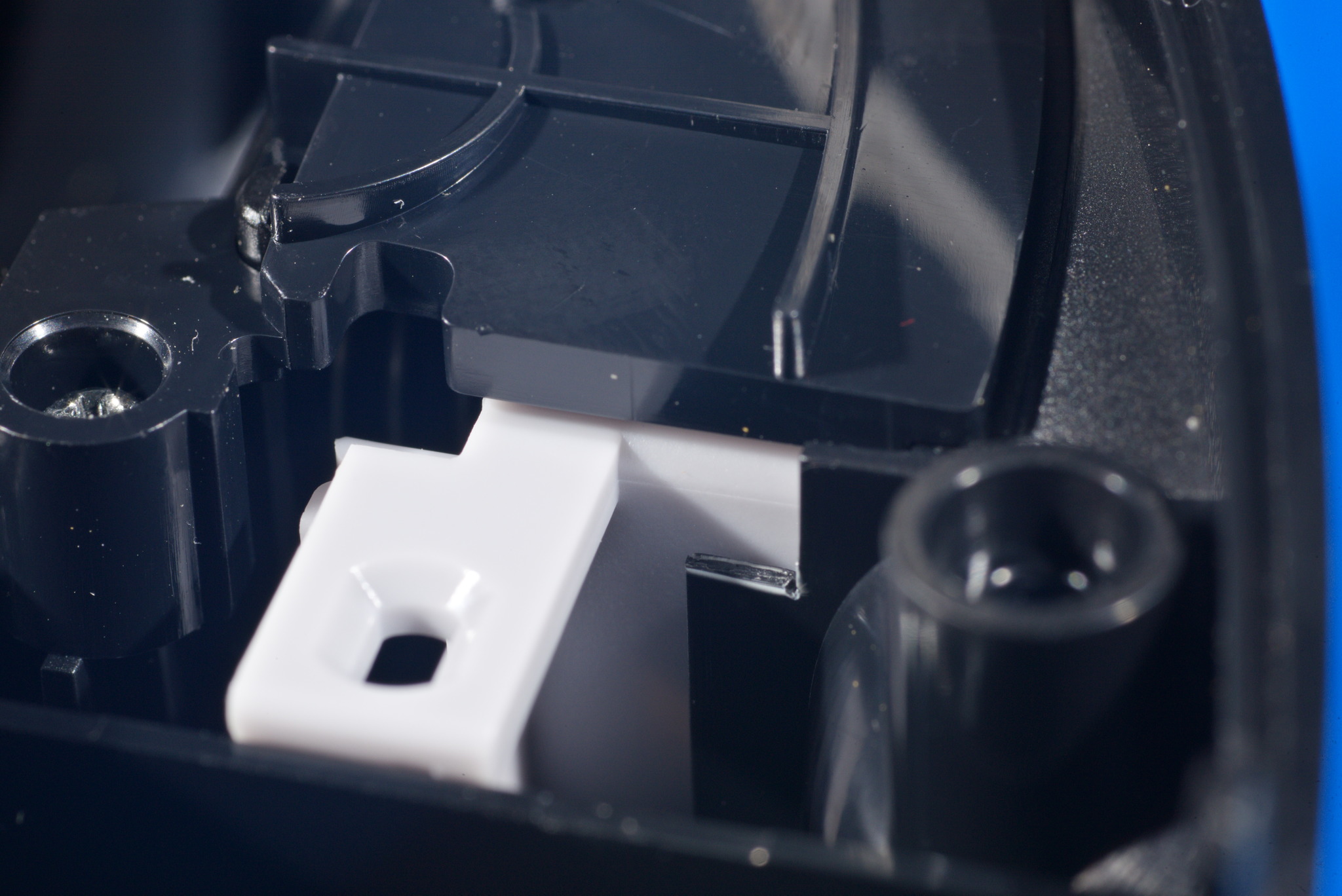
Begin by taking the backshell and marking a point 0.5 inches or 13 mm down directly below the edge, aligned with the center of this tab.
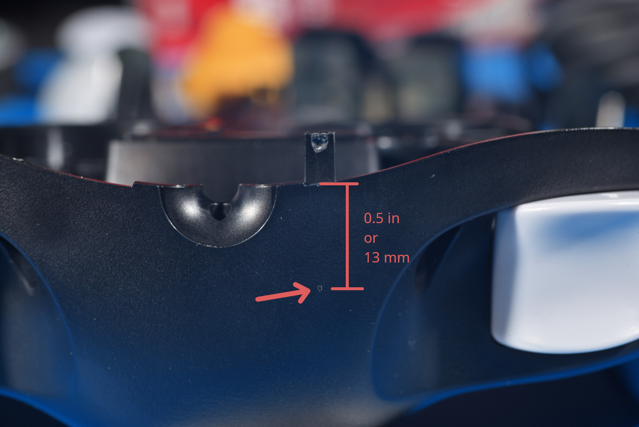
Using a split-point drill bit to help prevent the bit from wandering around, drill a 7mm diameter hole in the back of the controller.
You may also use a 9/32” bit or a Letter J drill bit.
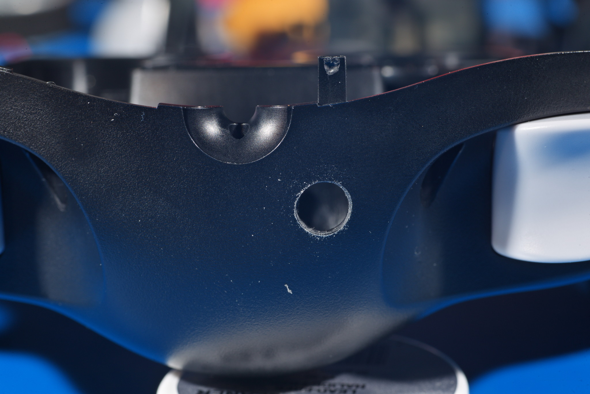
Note that on this particular shell, the bit wandered slightly towards the centerline of the controller, which is fine.
If the bit wanders towards the side of the controller, you may need to carve out the area marked in red to provide clearance for the TRRS jack’s flange.
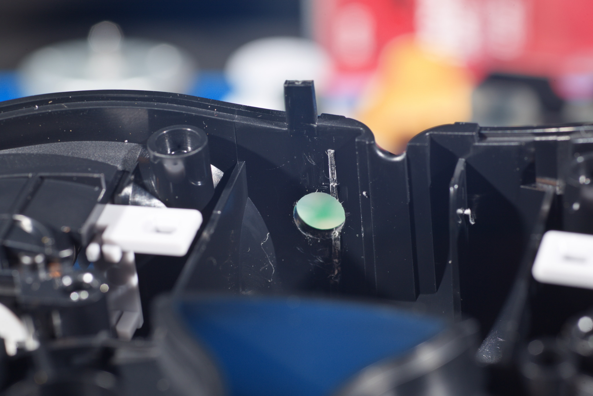
In this case, the hole instead intersects a rib that only exists on T3 shells that you should remove in the vicinity of the hole.
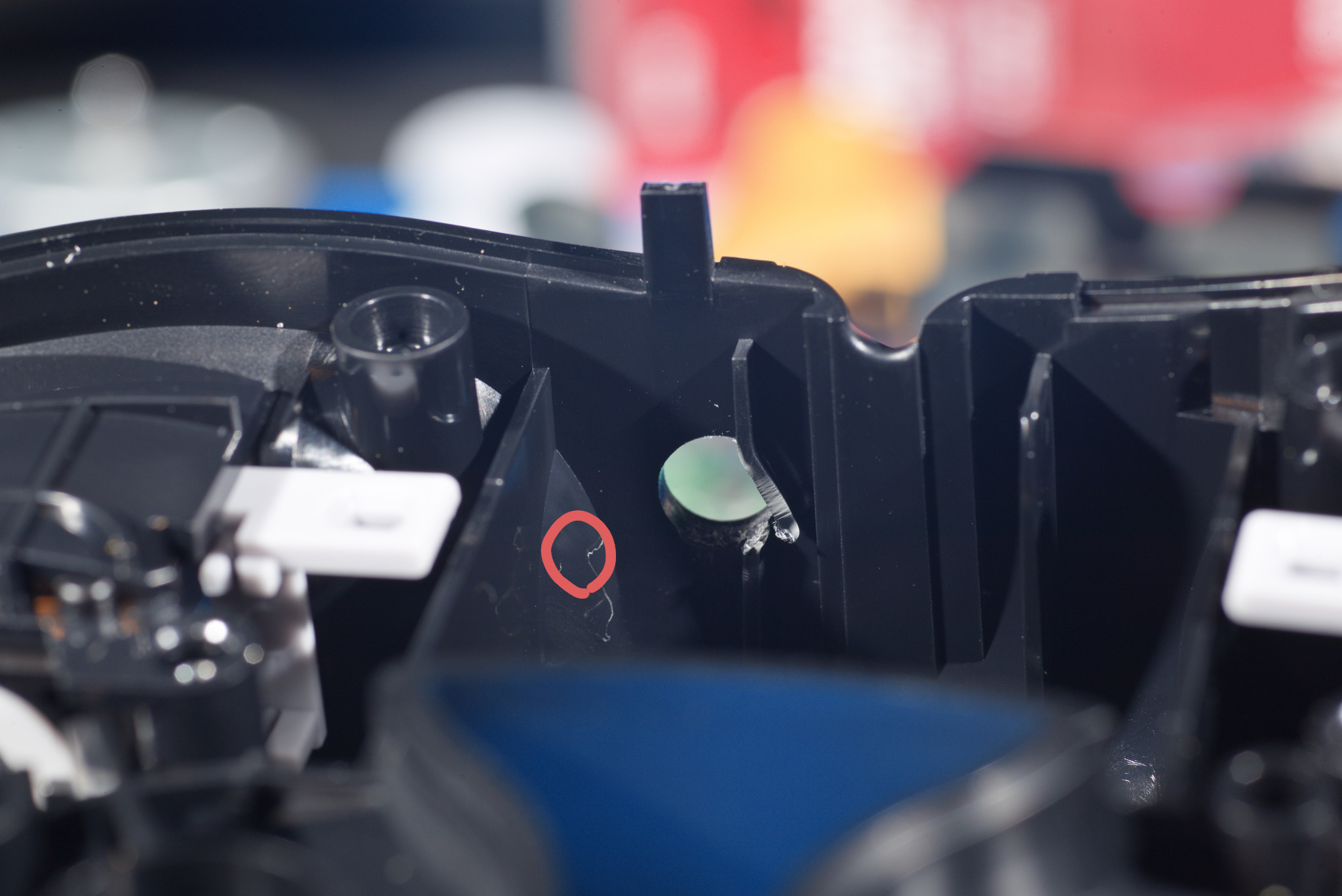
Simply cut the rib off with flush cutters.
Video Guide for jack, connector, and wire prep
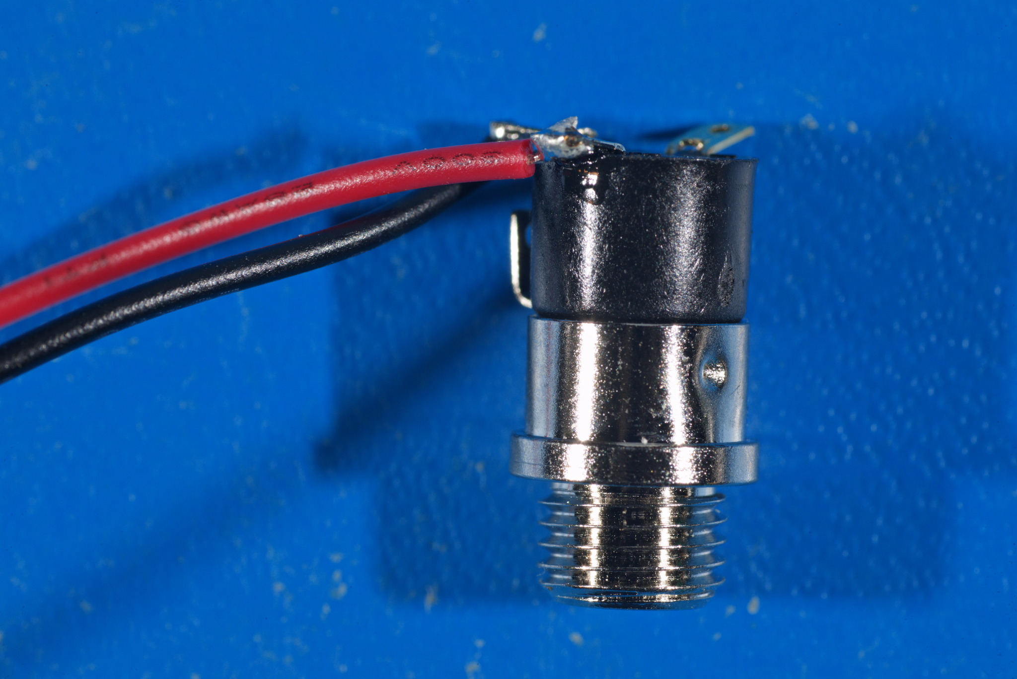
Next up we must prepare the 3.5mm TRRS jack for installation.
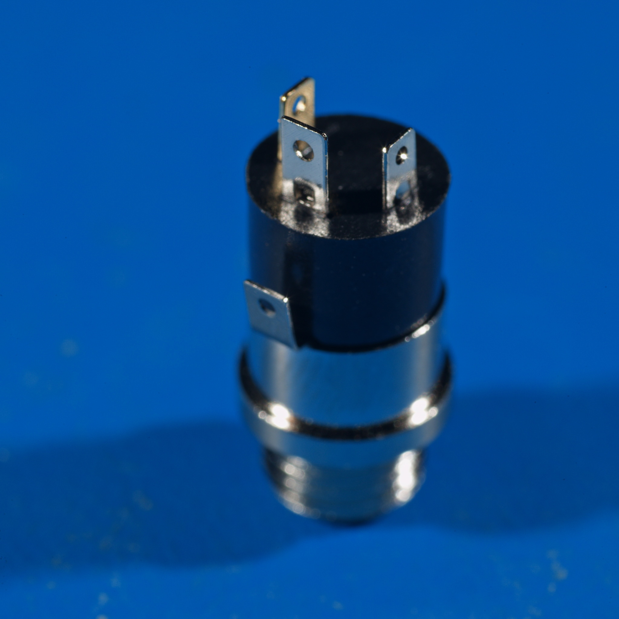
To get the jack to fit with an OEM rumble motor, use pliers to bend the tabs on the end sideways.
Note which tabs are used for what.
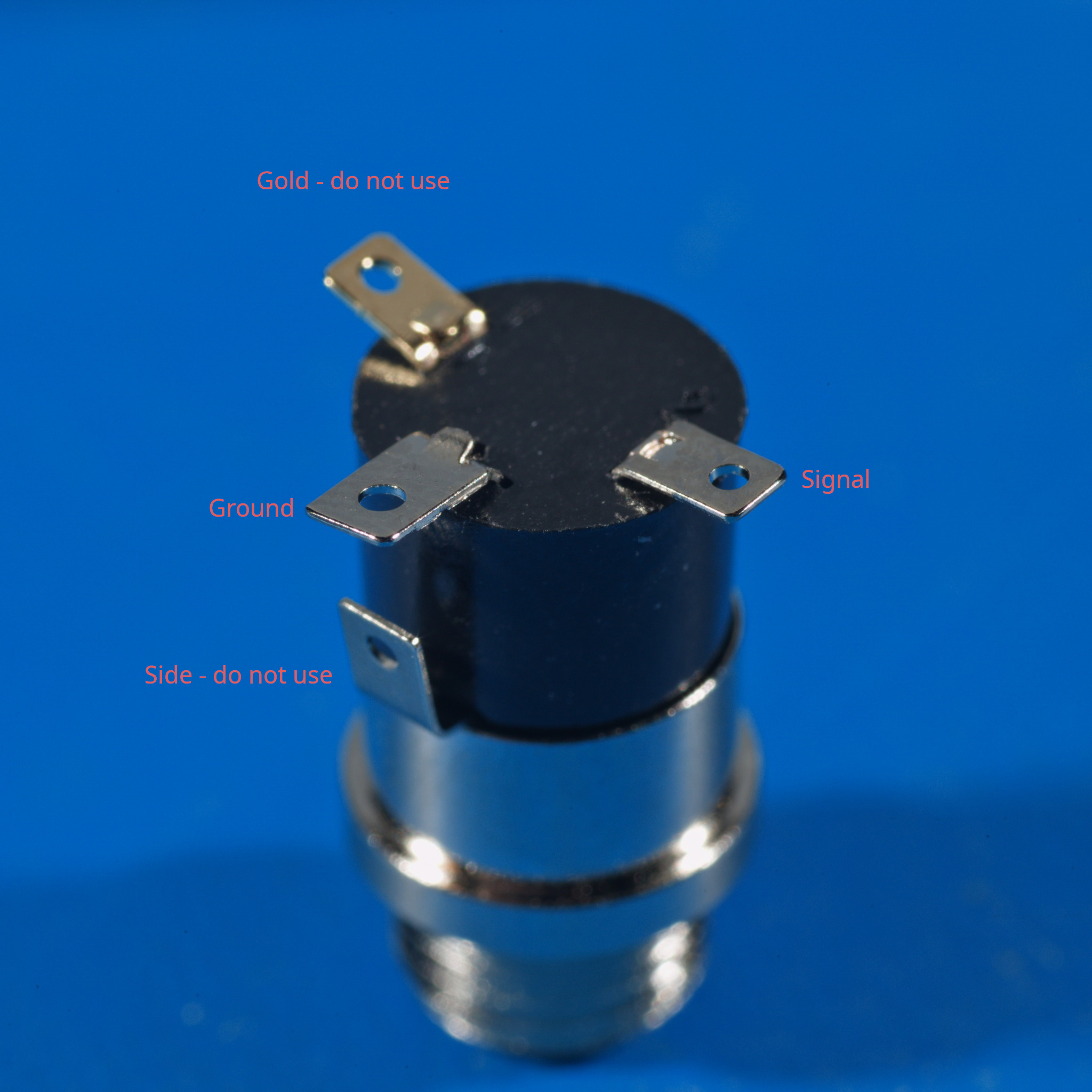
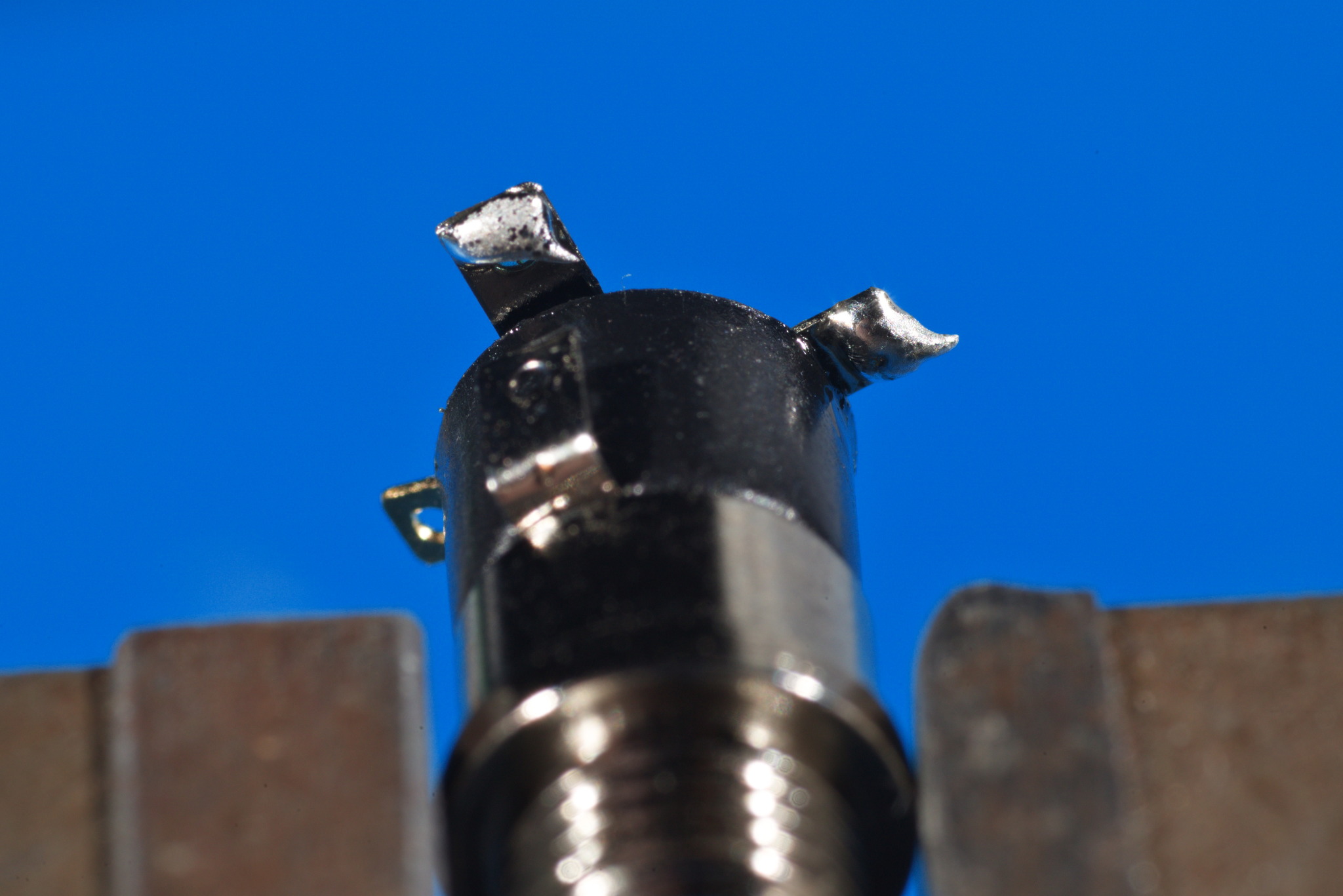
Apply flux to the two bent silver tabs and tin them generously with solder.
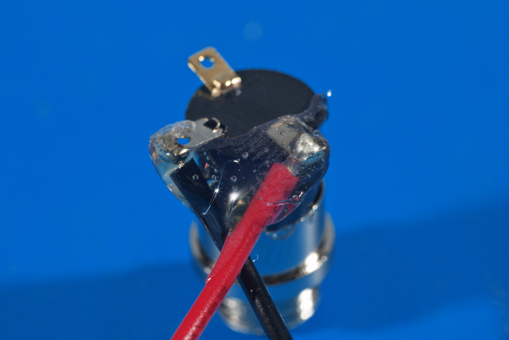
Cut a two-pin JST-PH pigtail’s wires to 3 inches long (75mm), strip the ends, and apply flux. Shorter wires give less slack when maneuvering, and longer wires are hard to fit, so be fairly precise with the length here.
Then solder them to the two tinned tabs.
Make sure that the black wire goes to the middle tab, and the red wire goes to the other silver tab.
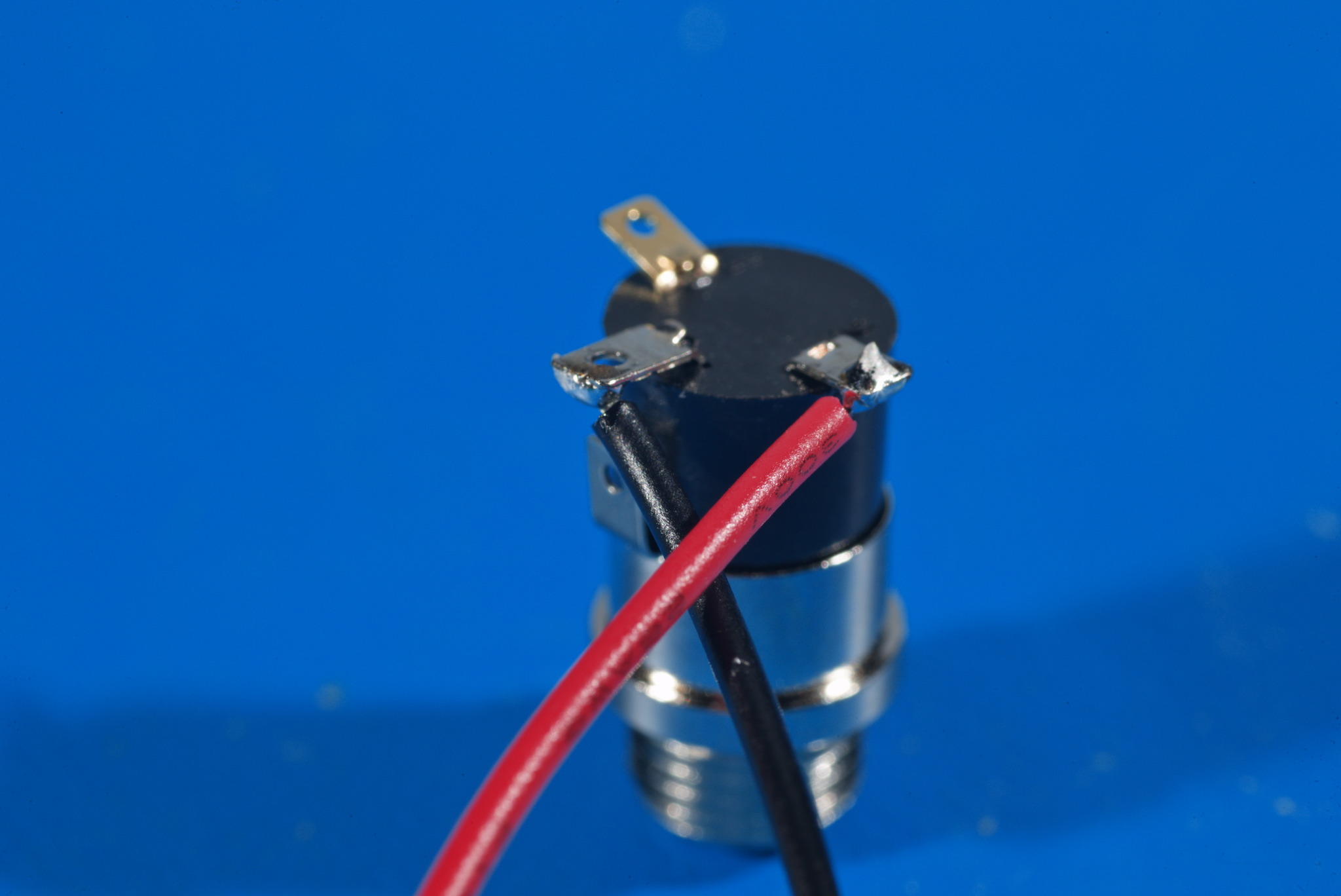
Make sure the wires are soldered to the back side of the tabs so that they do not stick out past the end.
Generously apply hot glue between the wires and the barrel of the TRRS jack in order to provide strain relief.
Again, do not let it protrude much past the end of the jack.
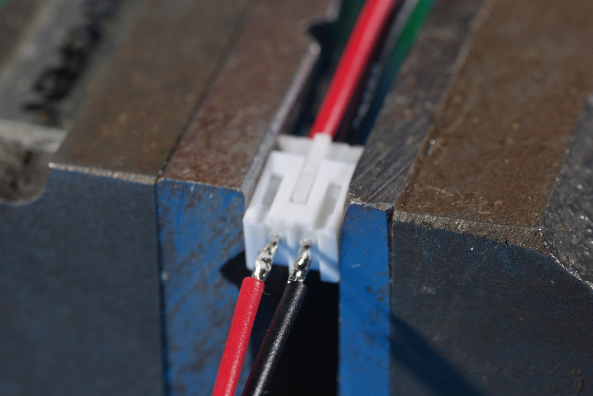
Next, cut 1.5” (38mm) long wires, strip both ends, and apply flux. Shorter wires might not reach, and longer can interfere with closing the controller, so be precise with the length here.
Take the JST-PH receptacle and install it on the pigtail for support, then tin the protruding leads and solder them to the 1.25” wires. You must leave the connector in the receptacle while soldering, or else the pins will lose alignment as the plastic around them softens.
Make sure to match red with red and black with black; I used the scrap ends of the pigtail wires for this so the colors match nicely.
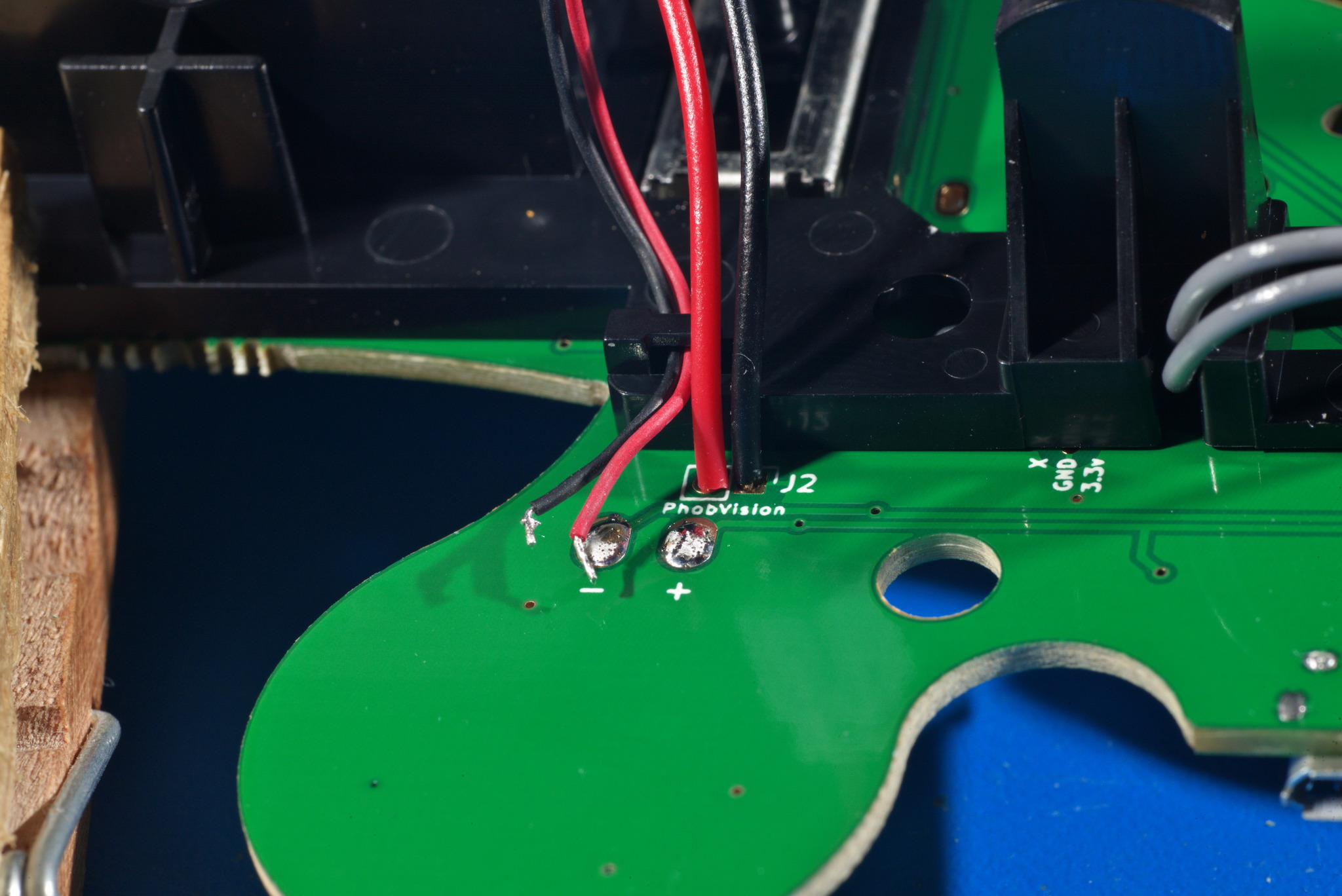
Video Guide for wiring to motherboard
Insert the receptacle’s wires into the back of the motherboard at the J2 through-hole pads, and solder them on the front of the motherboard.
Video Guide for soldering rumble motor
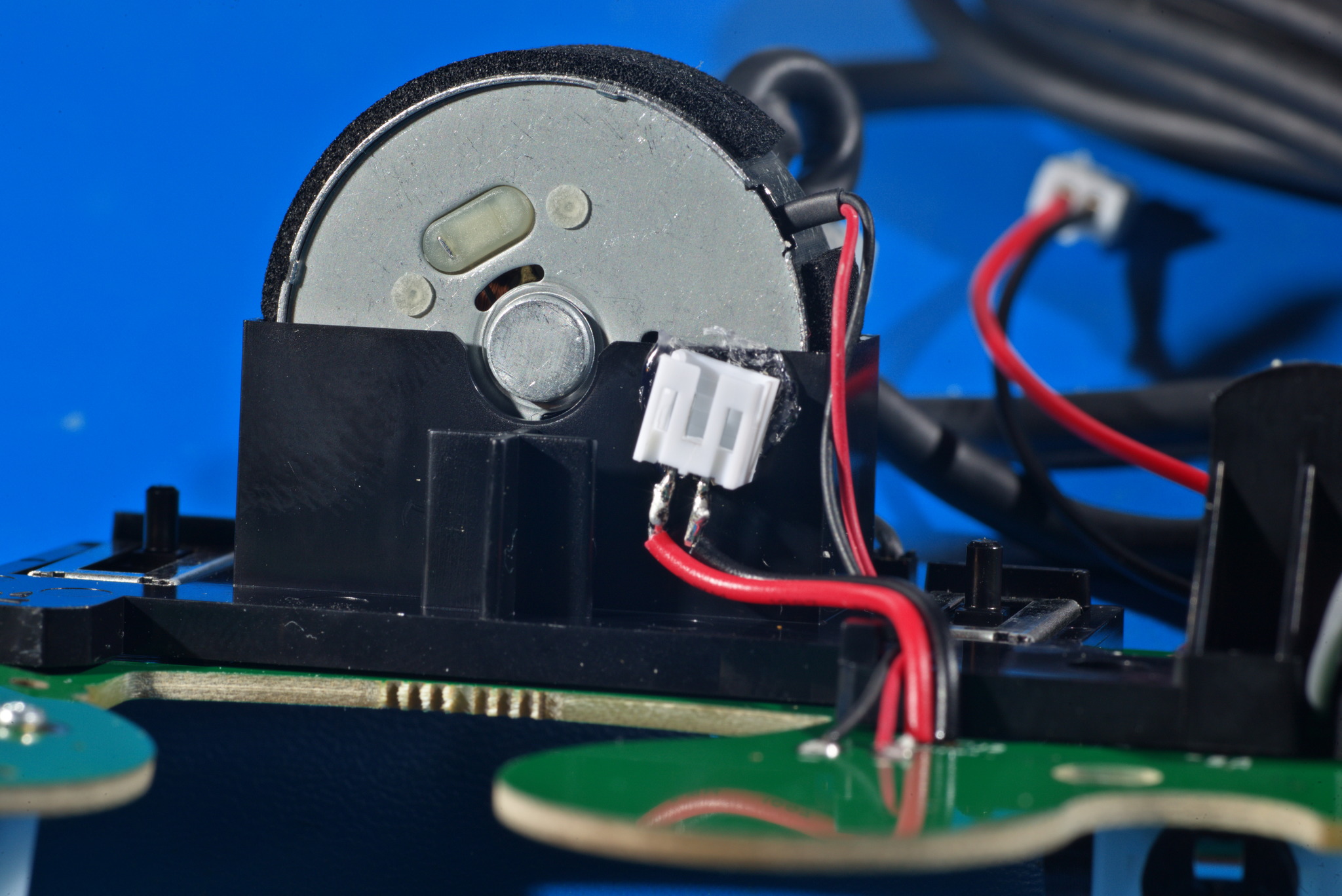
At this point, if you are installing rumble, mount the rumble motor in the rumble bracket by inserting it into the rectangular box. Make sure that the shaft is on the cable side, and the motor is rotated so that the wires are on the D-pad side, close to the edge of the box.
First, tin the rumble pads with a puddle of solder, then melt the puddle with your iron and use tweezers to hold the wire in the molten pool of solder. Remove the iron, and keep the wire still as the solder cools. Tuck the rumble wires in the clip on the rumble bracket.
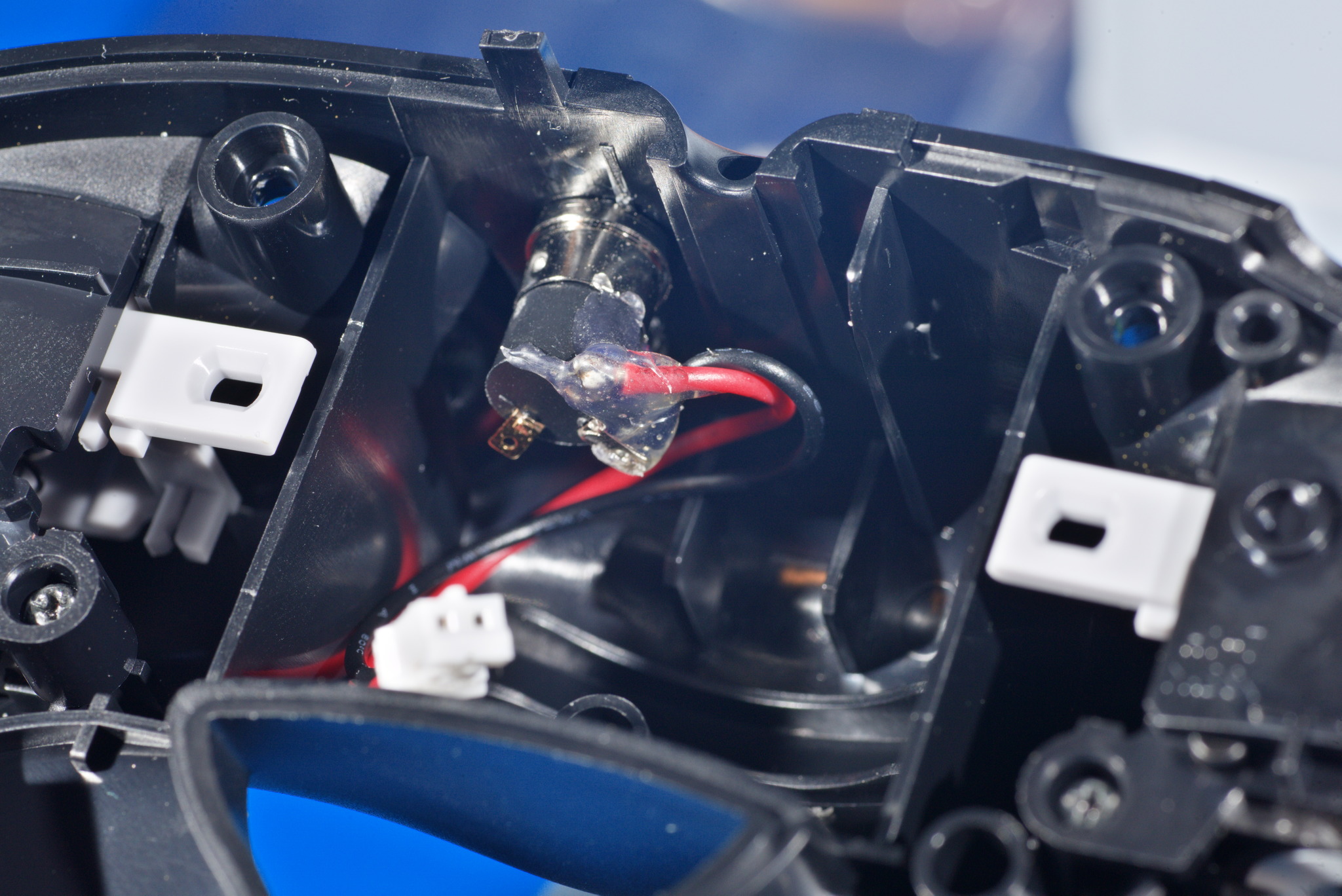
Then hot glue the PhobVision JST receptacle to the rumble bracket like depicted, ensuring that the opening is not blocked by the glue.
Video Guide for installing jack in backshell
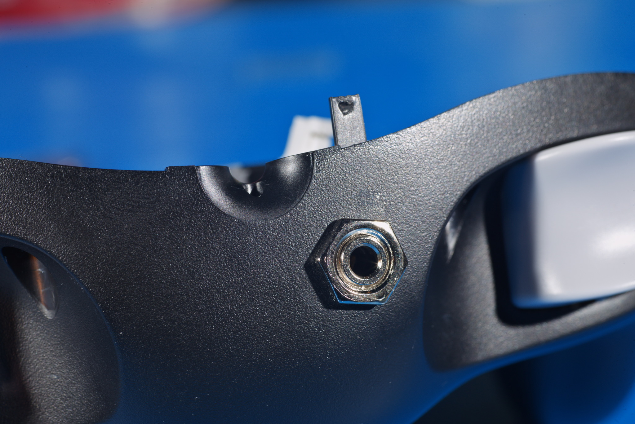
Next, install the TRRS jack in the backshell and install the nut on the outside using pliers.
I recommend you orient the jack so that the wires initially go towards the center of the controller, then loop around towards the triggers.
Rumble Motor Soldering
If you haven’t installed PhobVision, mount the rumble motor in the rumble bracket by inserting it into the rectangular box. Make sure that the shaft is on the cable side, and the motor is rotated so that the wires are on the D-pad side, close to the edge of the box.
Completion and next steps
Now your PhobGCC should be complete!
Reassemble your controller, and follow the Initial Setup procedure in the PhobGCC Calibration Guide for the version of the software you have flashed on the RP2040.
And, enjoy!
 This work is licensed under a Creative Commons Attribution-ShareAlike 4.0 International License.