Board Fixes
This is a document with illustrations that show you suggested fixes for some issues seen on PhobGCC Boards
Please ask in the PhobGCC Discord Server if you have any questions.
Full Duplex - PhobGCC v1.0/1.1
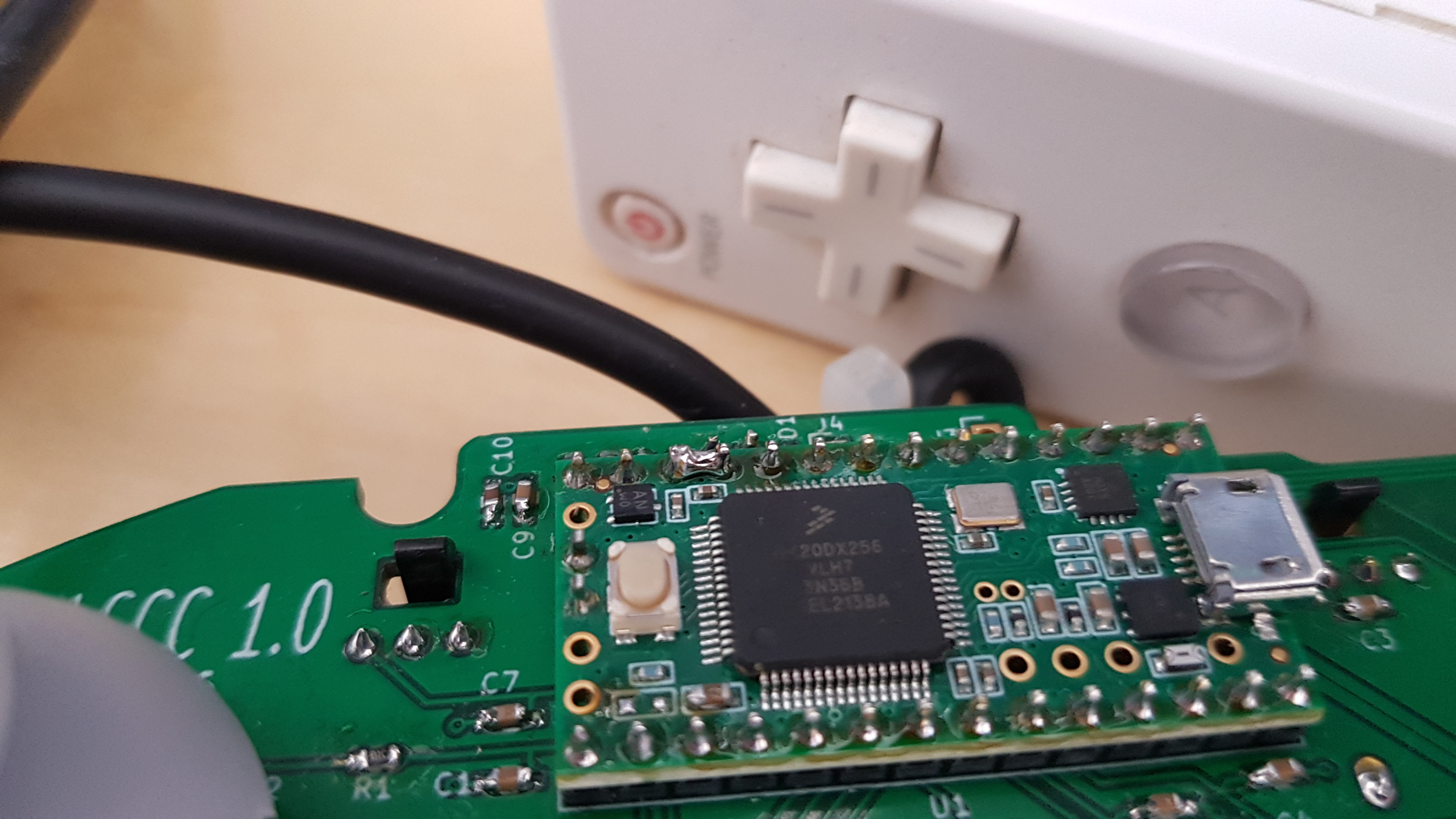
Bridge the third and fourth pins on the top left of the Teensy 3.2/Teensy 4.0 (as seen below) and flash the proper Diode_Short version of the firmware.
L-stick Hall Sensor Joints - PhobGCC v1.X
Due to the reversed orientation of the left stickbox on PhobGCC v1.Xs, the left trigger guard applies significant pressure to the hall effect sensor joints. This can deform the solder joints if leaded solder, which is soft, was used.
The way to do them right is to cut the pins flush and reflow them per the build guide.
There are 3 other fixes that resolve the issue.
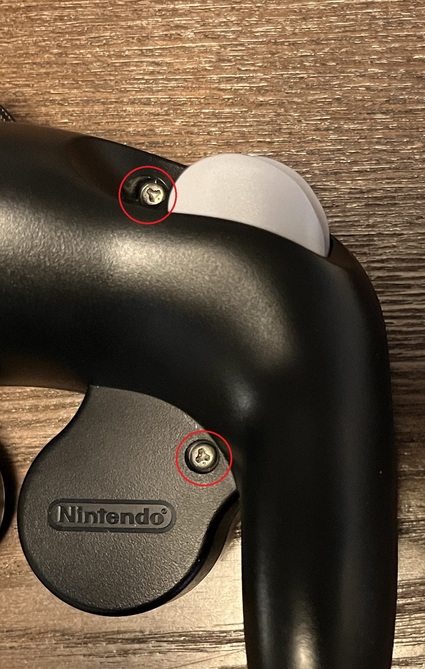
Temporarily - unscrew the shell screws by 3/4s of a turn.
Unscrew the following screws 3/4s of a turn so that it takes off the pressure on the hall sensor joints.
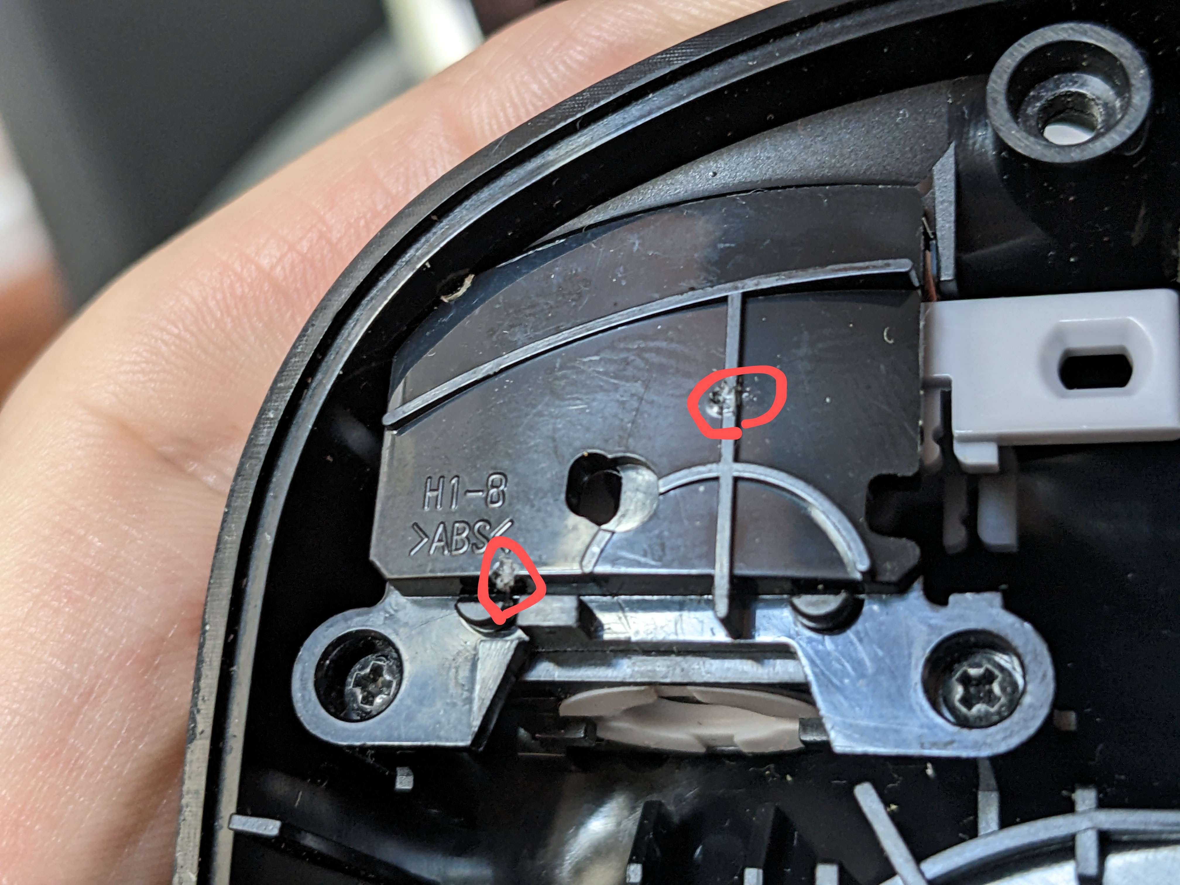
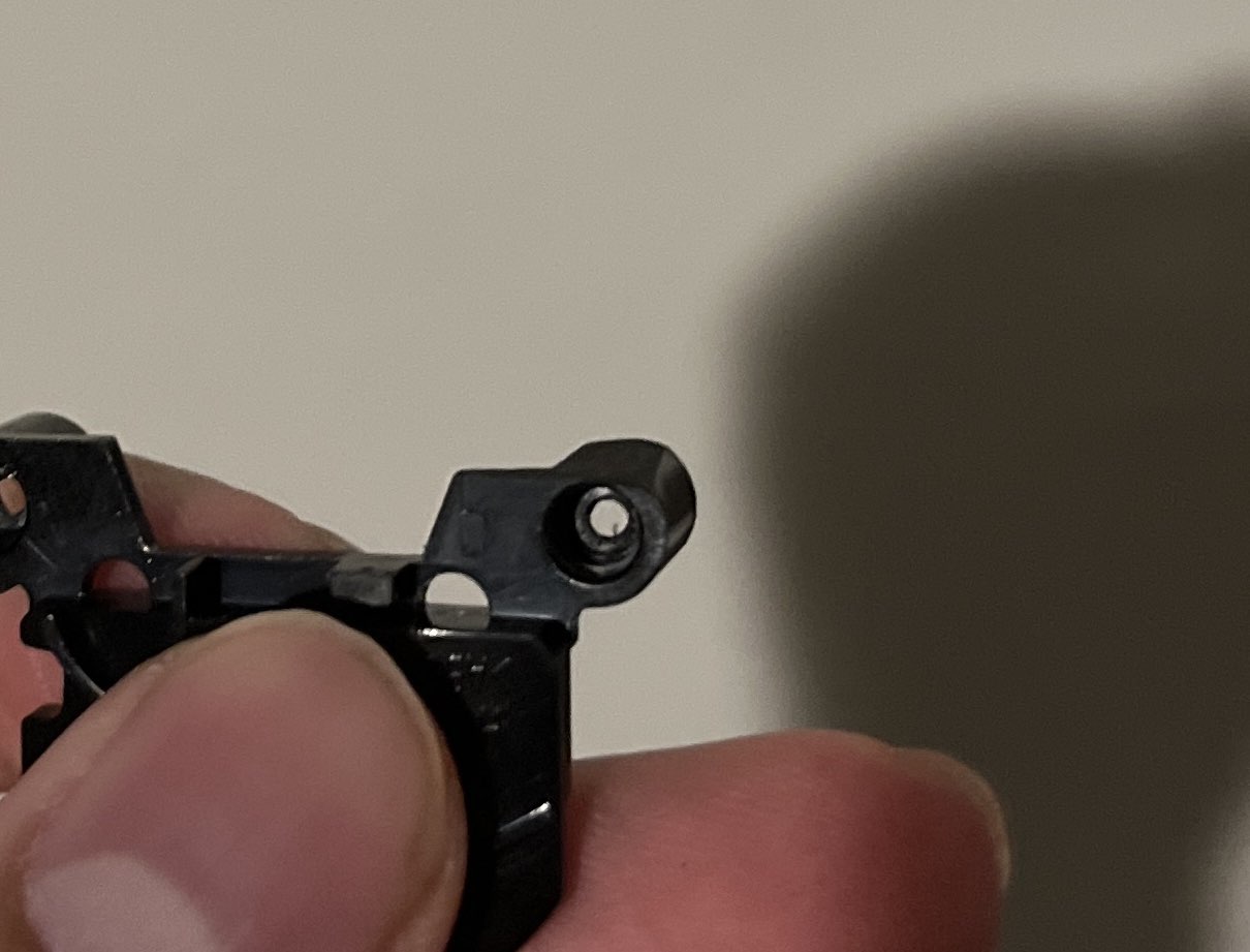
Filing - File down the trigger guard at the circled points.
Take out the two black screws holding it in place and remove the trigger guard. Proceed to file down the left trigger guard in the circled locations below to ensure that the joints are not being stressed.
3D Print - Either 3D print yourself or order the 3D printed bracket from a service such as JLC and swap it out.
L-Stick Interference with L-slider - PhobGCC v1.X
As a result of the hall effect sensor placement, the analog stick is positioned upside down. This causes the notch in the skirt of the analog stick to not line up with the solder joint of the analog slider. There are 3 fixes that resolve the issue.
During Assembly - Trim the pin flush with the hole and only add a little solder so that the solder wets into the hole. This should result in a flat board on top where it does not interfere with the analog stick.
After Assembly - trim the pin flush and reflow the solder so that it wets into the hole.
Cutting - Trim the skirt as the other side of the stick so that it does not interfere with the solder joint of the analog slider. You want to replicate the cut-out that is already on the other side of the analog stick.
L-trigger JST Interference - PhobGCC v2.0.2
The placement of the L trigger holes on PhobGCC 2.0.2 is too high and interferes with the L trigger guard when installing a JST header. There are 3 fixes that resolve the issue:
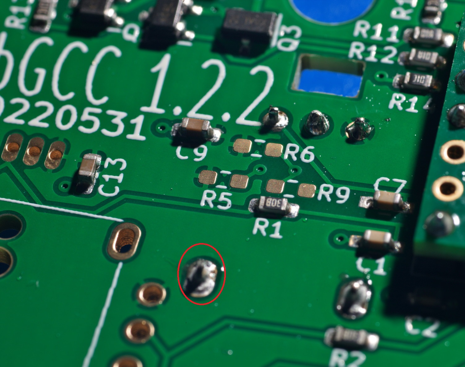
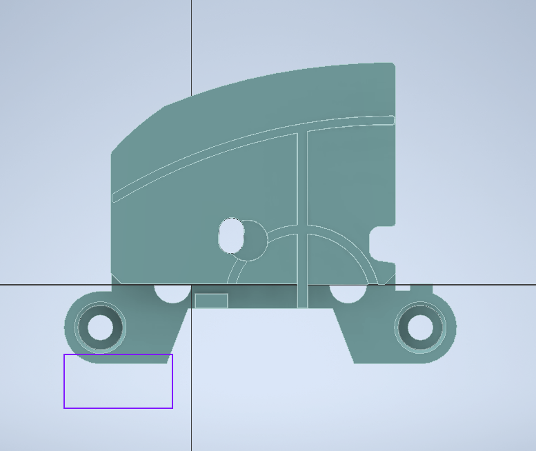
Filing - File down the trigger guard at the bottom of the left screw post so that it is flush with the hole as shown below. You only need to remove 0.25mm of material.
3D Print - Either 3D print yourself or order the 3D printed bracket from a service such as JLC and swap it out.