PhobGCC Buying Guide: How to Evaluate a Phob
So you want to buy a PhobGCC, but you may not know what to look for, and you may not know how experienced the seller is at making them. We on the PhobGCC team are planning on vetting Phob makers in the hopes that there will be people you can trust, but not everyone making them will be certified. It is an open project, after all.
This is especially important if you’re buying used, since you may not know who assembled it at all.
This guide aims to show you what to check for, ideally before you buy. If buying in-person, ask the seller to take it apart to show you if they’re not on our list.
Easy Things to Look For
This section is for things that are simple to verify without technical knowledge: whether it works, and important part selection.
What Version
PhobGCC comes in several board revisions, which are identifiable by the number following the PhobGCC name. Some are much more common than others.
Which board version you have affects how you update the firmware.
1.0
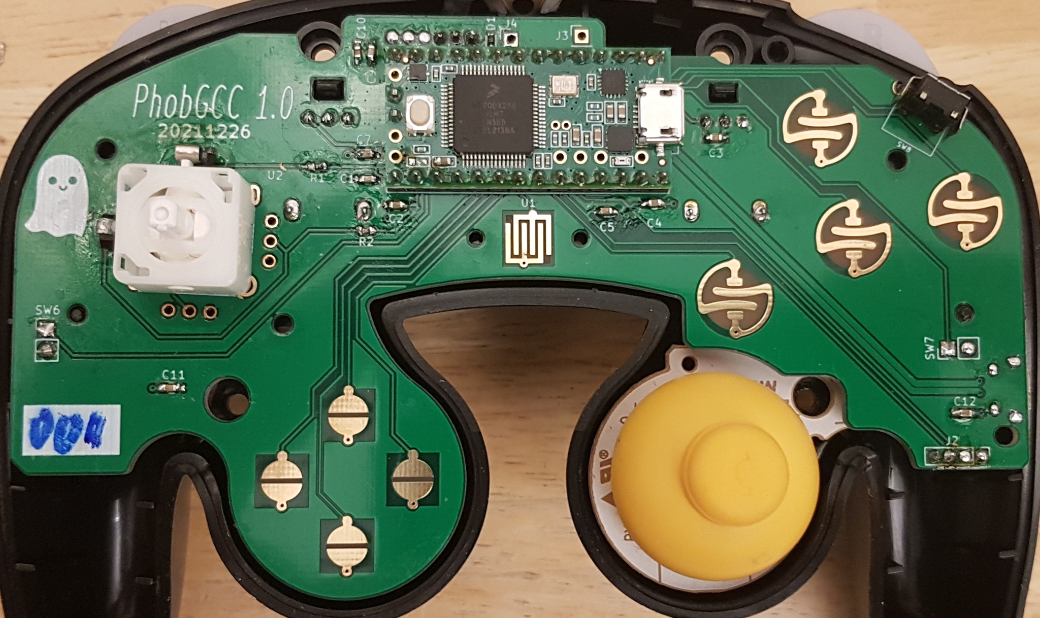
- Very rare.
- Has no rumble.
- Has no support for Hall-effect C-sticks.
1.1
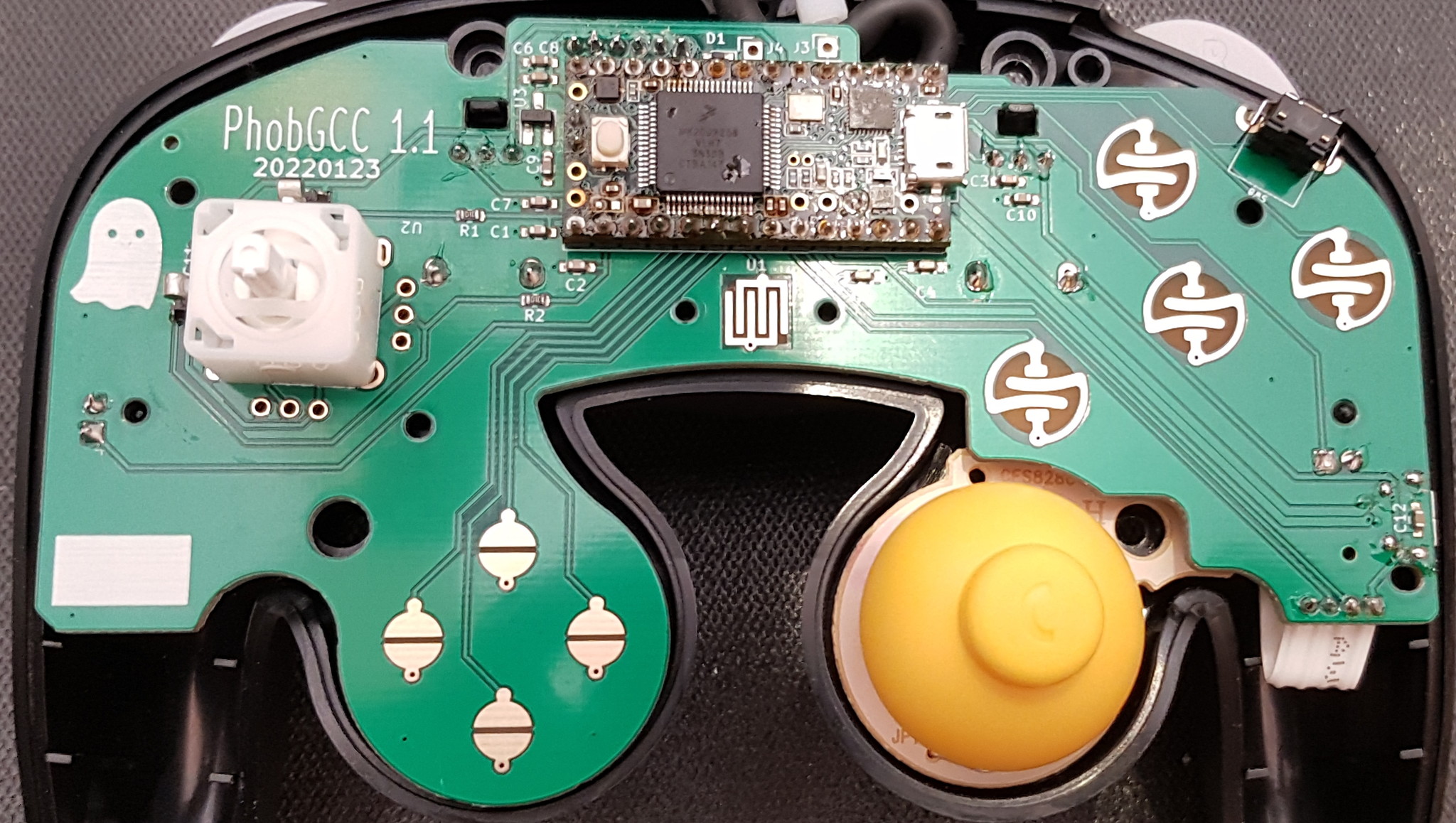
- Somewhat common.
- Has no rumble.
- Has support for Hall-effect C-sticks. The above photo has a potentiometer C-stick board from an OEM controller; this is not desirable.
- Exists in three variants with the same board, but each needs its own individual firmware:
- Teensy 3.2: the standard version, where the main chip on the Teensy has many visible legs on all four sides. Not that common due to a Teensy 3.2 shortage.
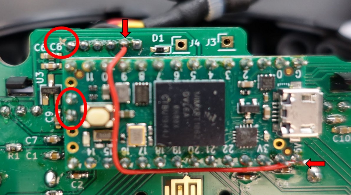
- Teensy 4.0: an alternate microcontroller option that can be distinguished by having no legs. These also have a wire added by hand going across the Teensy board. See photo below for what a Teensy 4 looks like on a PhobGCC 1.1.
- Teensy 4.0 with Diode Fix: similar to above, but pins 7 and 8 on the Teensy may be shorted, or the diode next to the connector may be shorted.
1.2:
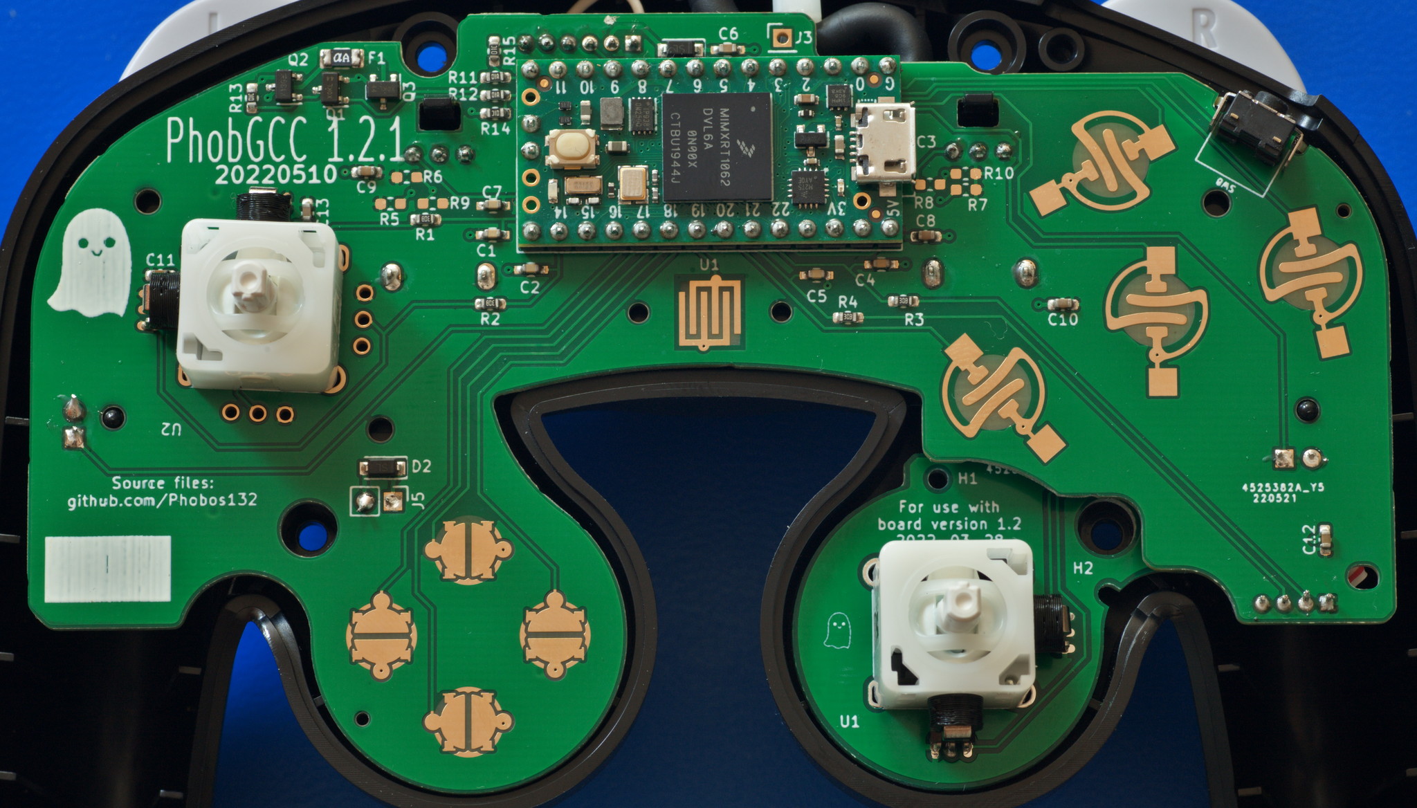

- Has rumble support.
- Has mouse button support on the face buttons other than Start.
- Exists in three different board variants with shared firmware support.
- 1.2: A handful of prototypes exist.
- 1.2.1: A few resistor/capacitor values were changed. Only a few prototypes exist.
- 1.2.2: Wide release. D-pad, Hall sensor, and rumble motor contacts were changed. C-stick and mouse-button-supporting L/R paddles come attached to the main board to ensure all Phobs have no OEM C-stick boards.
Some customized versions may exist, but all are required by the license to remove the Phob Ghost icon and the PhobGCC name. Ask the seller for info on what versions they were based on.
Functionality
Obviously, the controller should work. All buttons, triggers soft and hard (unless explicitly modified to remove soft-press), d-pad, and control sticks. If the board is version 1.2 or later, rumble should function too.
If trigger hard press is disabled in hardware, then many aspects of controller configuration will be impossible.
The sticks should not be very noisy or jittery when held off-center, but jitter between two adjacent values is acceptable. Notches should have repeatable coordinates when entered from the same direction, though they may have different coordinates if entered differently (clockwise, counterclockwise, straight from the center).
The controller should be set up so that it doesn’t have snapback. You can test this in game, but ideally you can run Smashscope on a Wii+480i CRT to see graphs.
Stickbox
The stickboxes which contain the stick mechanism should be T3, which are entirely white plastic and mounted with two screws on the underside of each.
T1/T2 stickboxes, which have metal frames around plastic innards, are far more prone to wear and becoming loose. Additionally, they are soldered down, making them difficult to replace. This effectively limits the lifespan of a PhobGCC.
C-Stick Board
The C-Stick board should be a PhobGCC one with magnets, rather than an OEM C-Stick board with potentiometers.
While an OEM C-Stick can function when new, the PhobGCC is not designed to gracefully handle any PODE that develops in the potentiometers, and you will get misinputs as the stick wears.
This also limits the lifespan of a PhobGCC, although it is not difficult for an experienced Phob maker to remedy if they have the parts.
USB Cable
If your PhobGCC came with mouse button switches installed for ABXY, the Y button gets in the way of the USB port on the Teensy and the seller should include a right-angle or 180 degree USB cable that clears the mouse button switches.
Intermediate Things to Look For
Here is where we begin evaluating the quality of the work.
Soldering Workmanship
Shorts
There must be no connections made between pads that are close together. You should be able to see green completely separating the solder.
Solder Joint Shininess
It is commonly believed that solder joints are supposed to be shiny, but that mainly applies to leaded solder (Sn63 or Sn60), not lead-free solder (such as SAC305). Most commercial products these days use SAC305 or similar due to regulations, but Sn63 is still often preferred by hobbyists for its ease of use.
Ask your vendor what kind of solder the PhobGCC you are evaluating was made with before judging the joint quality by how shiny they are.
Solder Bonding
All solder joints should have the solder clearly sticking to both the component and the board in order to make a strong physical and electrical connection.
Solder Quantity
The entire pad on the board should be wet out with solder, but there ideally should not be enough solder to form a convex ball.
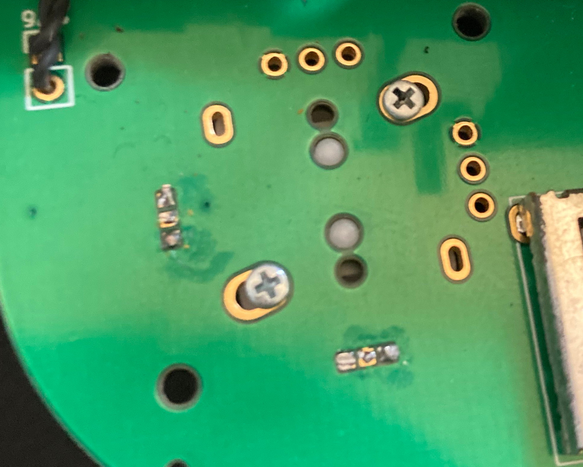
This is an example of a solder joint that has poor contact with the board and caused undesirable stick behavior.
Physical Workmanship
Solder Joint Height
The pins below the Teensy must not protrude below the bottom of the board or else they will interfere with the plastic rumble bracket.
Likewise, the solder joints for the Hall effect sensors for the main stick should be cut fairly close to the PCB or else they will make it difficult to close the controller.
 This work is licensed under a Creative Commons Attribution-ShareAlike 4.0 International License.